2025 — Prom-nasos.com.ua
December 8, 2025
Pump flow control diagram during decanting

Decanter centrifuges are used for separating mixtures, emulsions, and various products into solid and liquid fractions by means of centrifugal force.
These units are widely used in various industries — chemical, food, mining, pharmaceutical, etc. Accordingly, the range of processed liquids is very broad.
To achieve the highest efficiency of the decanter, it is important to feed the product at a constant, stable flow rate, because if the volume of liquid supplied to the decanter fluctuates, the output products will have varying properties (the moisture content of the solid phase and the clarity/purity of the liquid fraction will constantly change).
The diagram below shows an example of maintaining a constant, stable flow rate using a flow meter (specifically, a rotameter with a milliamp signal).
This simplified diagram illustrates the principle of maintaining a constant supply of soybean oil to the decanter.
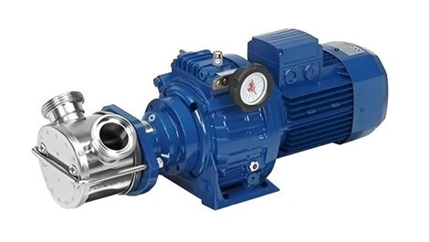
The product is fed to the decanter by means of a cantilever stainless steel pump . A rotameter with a 4–20 mA signal is installed on the supply pipeline; the signal transmitted by the rotameter to the control unit allows the pump speed to be adjusted in order to maintain a constant flow rate, thereby ensuring the highest quality of the output products.

December 5, 2025
Masts for wind turbines
The installation of a wind turbine requires a mast (tower) on which it will be mounted. The height and design of the mast are calculated individually for each case.
The designs of vertical supports can vary significantly.
Guyed mast
This type of support is used for horizontal-axis wind turbines with a capacity of up to 10 kW.
Advantages:
low cost due to the use of pipes and profiles with a smaller cross-section;
possibility of installation without using a crane.
Disadvantages:
occupies a large area, since the guy wires must be anchored around the mast at a specific angle;
lower reliability compared to other types of supports;
requires maintenance.
Segmented mast
The support for a wind turbine consists of several segments (pipes of different diameters). The segments are connected to each other with flanges.
This type of structure is used for installing wind turbines across a wide power range. The mast height can reach 36–40 m.
Advantages:
high structural reliability;
simple and fast installation;
does not require maintenance.
Disadvantages:
the need to use a crane to install the wind turbine;
relatively high cost, as thick-walled pipes or profiles are used.
Monolithic conical mast
The vertical support is manufactured by welding steel strips into a hexagonal or octagonal shape.
The support is a solid conical structure with two flanges: a base flange for mounting to the foundation and a flange for mounting the wind turbine. The height of the support is limited to 12 m.
Advantages:
high structural reliability;
fastest installation;
does not require maintenance.
Disadvantages:
the need to use a crane to install the wind turbine, as well as transportation difficulties, since the support is non-dismantlable;
relatively high cost due to the use of thick-walled pipes or profiles.
Lattice mast
This is a mast manufactured using standard structural steel sections (angle steel, square or rectangular tube, round tube, etc.).
The mast height can range from 12 to 36 m.
Advantages:
high structural reliability;
does not require maintenance.
Disadvantages:
the need for welding work;
complexity of manufacturing.
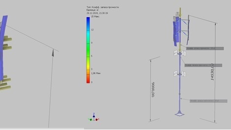
Each structure requires an individual approach and is calculated for strength, rigidity, and stability.
When calculating the support, the main input data are the mass of the wind turbine, the mast height, and the wind pressure in the region where the wind turbine will be installed.
December 3, 2025
New series of impeller pumps from Italian manufacturer LIVERANI
LIVERANI impeller pumps are low-speed rotary pumps made of stainless steel with a flexible impeller. They are especially suitable for pumping delicate, fragile, and viscous liquids, as well as liquids containing solid particles in suspension.
LIVERANI pumps are widely used in the ECOLOGICAL sector (wine, must, grape must and destemmed grapes), in the FOOD INDUSTRY (beer, fruit pulp and juice, honey, liquid sugar, syrups, glucose, milk, melted butter, yogurt, liquid eggs, oil, tomato pulp and juice, brine, etc.), in the CHEMICAL INDUSTRY (starch, water-based adhesives, emulsions, glycerin, wax, detergents, rubber latex, photographic processing liquids, polyelectrolytes, paints, inks, industrial effluents, etc.), as well as in COSMETIC and PHARMACEUTICAL production (liquid soap, cleaning lotions, creams, shampoos, etc.).
Simple installation principle, a wide choice of materials and pump unit configurations
The quality systems applied throughout the entire production process allow us to offer a wide, versatile, and customized product range.
Each pump series can be manufactured with different types of impellers, mechanical seals, couplings, and in various configurations, namely:
pump with open shaft;
coaxial motorized pump (with an electric motor or an orbital hydraulic motor);
with gearbox;
with pulley (on a trolley or base);
with a mechanical speed variator or with a frequency converter.
December 1, 2025
Reasons for end seal and gland seal leakage
A mechanical seal or a reinforced lip seal (packing), according to the manufacturer’s instructions, does not require maintenance during operation. Undoubtedly, this is an exceptional advantage for anyone using a pump with such a sealing element. But there is one BUT!
The operating instructions for the product contain clear guidelines under which conditions the hydraulic part will maintain its tightness:
absence of “dry running,” i.e., operation of the pump without liquid present in the flow path. “Dry” operation is accompanied by rapid heating of the friction pairs and melting of the rubber bellows or rubber ring;
bearing wear leads to increased vibrations and impact loads on the seal’s friction pairs, resulting in leakage and possible subsequent flooding of the electric motor;
pumping liquids that contain abrasives or inclusions that may damage the seal;
ignoring the need to flush the pump after completion of operation. When pumping liquids prone to crystallization or sticking, the pump should be flushed to prevent the friction pairs from sticking together or the edge of the rubber packing lip from adhering to the shaft.
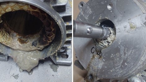
In the photos below, you can observe the consequences of packing leakage. When pumping milk, the containers were emptied “to zero,” followed by dry running. Pump flushing was also not performed.
As can be seen in the photos, the pump was operated for a long time after the packing began to leak. This led to the need to rewind the motor, replace the bearings, and replace the packing.
November 28, 2025
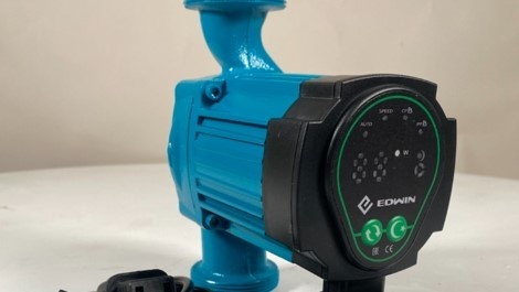
The HRS32/7 circulation pump – a quiet and reliable solution for your heating system
Every heating system requires a pump that ensures stable circulation of the heat transfer fluid. Without it, heat simply does not reach all radiators, and the boiler operates inefficiently.
One of the best options for residential and small commercial systems is the HRS32/7 circulation pump with a wet rotor . It is a simple, reliable, and proven solution that has shown excellent results in practice.
What is the HRS32/7 pump and how does it work?
This pump features a wet rotor, meaning the rotating components are in contact with the liquid inside the system. As a result, the heat transfer fluid lubricates and cools the mechanism itself, so the pump requires no additional maintenance and operates almost silently.
The HRS32/7 is designed for continuous circulation of water or heat transfer fluid in heating and domestic hot water systems. Its construction is optimized to ensure stable pressure even in branched, multi-floor installations.
Main specifications
Connection size — DN32 (2")
Maximum head — up to 7 m
Flow rate — up to 3.7 m³/h
Three rotation speeds (manually adjustable)
Durable cast-iron housing
Low noise level
Advantages of the HRS32/7 pump
Quiet operation. The wet rotor ensures smooth performance without humming or vibrations. Ideal for residential spaces.
Energy efficiency. With three speed settings, you can choose the optimal mode and avoid unnecessary power consumption.
Durability and reliability. Its simple design allows the HRS32/7 to operate stably for many years without the need for frequent maintenance.
Easy installation. The pump can be easily integrated into standard heating systems — the threaded connections fit most pipes.
Availability of spare parts. This model is popular, so seals, nuts, and other spare components are easy to find on the market.
The HRS32/7 pump is ideal for:
heating systems in private homes;
underfloor heating;
domestic hot water circulation;
small commercial facilities.
Conclusion
If you are looking for a quiet, efficient, and reliable circulation pump for your heating system, the HRS32/7 is exactly what you need. It combines proven quality, a simple design, and a reasonable price.
The pump is available in our warehouse, and you can purchase the HRS32/7 directly on our website. If needed, we can also provide consultation on selection or installation.
The HRS32/7 circulation pump is a simple solution that works reliably for years.
November 24, 2025
BMS battery system lockout: why it happens and what to do about it

If the battery has stopped working, is not charging, or appears “dead”, even though everything seemed fine before — most likely the BMS protection has been triggered.
BMS is a Battery Management System. It ensures that all cells operate without overload, overheating, or short circuit. If something goes wrong, it simply “turns off” the battery to prevent damage to both the battery and the connected equipment.
Why the BMS locks
1. Over-discharge or overvoltage.
If even one cell is discharged below the allowed level or the voltage exceeds the norm, the system disconnects the battery. This is a common situation when the battery has been unused for a long time or is charged with an inverter that is too powerful.
2. Overheating or overcooling.
At temperatures below 0 °C, charging is prohibited because lithium crystals form inside the cells. In hot conditions above 50 °C, a lockout may also occur — to prevent ignition.
3. Excessive load or short circuit.
If the system “sees” that the current exceeds the allowed value, it disconnects instantly. This often happens due to improper inverter connection, especially if there are startup surges.
4. Cell balancing problems.
Over time, cells age unevenly and their voltages drift apart. The BMS detects this and reacts — especially during charging to 100%.
5. Loss of communication or firmware error.
In complex systems with CAN or RS485, any communication failure may cause a lockout, even if the cells themselves are fine.
How to unlock the system
1. Check the voltage at the terminals.
If the voltage is “0”, it does not mean the battery is empty. The BMS has simply disconnected the output. First, connect a control multimeter to each section or use the diagnostic port if available.
2. Try to “wake up” the BMS with a short charge.
In most cases, applying a small charging current (0,05–0,1 C) for a few minutes is enough for the system to exit sleep mode. Some LiFePO4 packs “wake up” even after a few seconds of applied voltage.
3. Cell balancing.
If the lockout is caused by voltage imbalance, the battery must be left on a charger in balancing mode (sometimes for several hours). The BMS will automatically level the cells and allow discharge.
4. Reset via service software.
Most “smart” BMS units (JBD, Daly, ANT, Seplos, Overkill Solar, etc.) have PC or smartphone apps. Through them, you can read errors and manually reset the lockout. However, it is important to eliminate the cause first, otherwise the system will lock again immediately.
5. Protection against deep discharge.
If the battery has been unused for a long time (especially for several months), the voltage may drop so low that the BMS “falls asleep”. In this case, you need a laboratory power supply with adjustable voltage to gradually “raise” the cells to a safe level.
6. Firmware update (for experienced users only).
If the BMS is “frozen” and unresponsive — re-flashing may help. However, do this only if you are confident in your skills, because a mistake can permanently damage the controller.
How to avoid repeated lockouts
Do not allow deep discharge — use a power management system or backup charging.
Do not use the battery in freezing temperatures without heating.
Every few months, check cell balance through the app or communication port.
If the battery is not in use, keep the charge level at 50–60% and store it in a dry place at +15…+25 °C.
And most importantly — never short the terminals manually in an attempt to “bypass” the BMS. This can cause smoke and burning smell.
Conclusion
BMS lockout is not a failure — it is protection from failure. It responds not to “whims”, but to real threats to the battery. If you understand the causes and act calmly, 90% of cases can be resolved without replacing the battery.
The main thing — do not panic, do not randomly poke wires, and always have a good multimeter or monitoring app at hand.
November 21, 2025
Butterfly valves: a reliable solution for modern pipelines
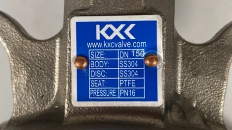
Today, in water supply, heating, ventilation, and industrial systems, butterfly valves — also known as disk valves — are used more and more often. These are compact and efficient fittings designed to shut off or regulate the flow of liquids or gases in pipelines.
Where butterfly valves are used
Such valves are used in:
water supply and sewage systems;
district heating networks and ventilation systems;
the food, chemical, and pharmaceutical industries;
installations using technical or seawater, as well as various industrial processes where reliable shut-off valves are required.
Thanks to their simple yet well-designed construction, a butterfly valve can be installed quickly even in hard-to-reach places — which is especially convenient for maintaining large systems.
Main advantages of butterfly valves
Compact size and low weight. Compared to traditional gate valves, these models take up less space and are easier to install.
Reliable operation. Tightness is ensured by a special sealing sleeve, which guarantees durability even under high pressure.
Easy maintenance. The design minimizes the risk of jamming, and replacing sealing components does not require complex tools.
Affordable price. Butterfly valves are significantly cheaper than traditional steel or cast-iron gate valves.
Option for manual or electric actuation. This allows their use in automated systems.
Ordering butterfly valves in our store
On our website prom-nasos.com.ua, you can order a butterfly valve at a competitive price. We offer certified products proven in practice, as well as expert consultations to help you choose a reliable solution for your specific working conditions.
Butterfly valves are an effective solution for those who need durability and ease of operation.
November 14, 2025
COLOMBO frame filter press
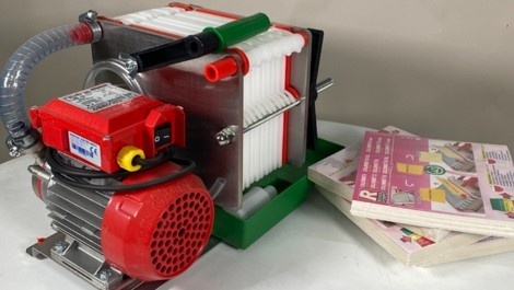
COLOMBO Frame Filter Press – a reliable solution for efficient filtration.
In any production process where it is necessary to separate liquid from solid particles, it is important to have equipment that operates reliably and without unnecessary complications. One such unit is the COLOMBO frame filter press, which has proven itself as dependable equipment for purifying suspensions across various industries — from the food sector to water treatment.
Purpose of the filter press
The COLOMBO filter press is designed for mechanical dewatering of sludge and for removing solid impurities from liquids. Its operating principle is simple yet highly effective: the suspension is fed into chambers between the filter plates, where it passes under pressure through the filter cloth. As a result, clean liquid (filtrate) is obtained on one side, and a dense solid cake (filtration “cake”) on the other.
Technical specifications (example: COLOMBO 12)
Design type: frame-plate
Number of plates: 12
Clamping system: manual
Filter cloth dimensions: standard, easy to replace
These parameters make this filter press convenient for use both in small enterprises and in agricultural applications.
Main advantages of COLOMBO
Ease of maintenance. The filter press design is well thought out: easy access to the plates, quick cloth replacement, and a minimum number of moving parts.
High filtration quality. Fine filtration ensures a very clean filtrate even when working with dense suspensions.
Durability. The materials used are resistant to corrosion, aggressive environments, and temperature fluctuations.
Cost-effectiveness. The filter press requires low energy consumption, and the use of consumables is minimal.
Versatility. Suitable for the food, chemical, pharmaceutical, and other industries.
Compact design. Takes up little space, which is beneficial for production areas with limited room.
This filter press is available in our warehouse, so there is no need to wait for delivery. You can purchase it today and put it into operation immediately.
November 11, 2025
Alpha-amylase and glucoamylase

Alpha-amylase and glucoamylase are enzymes used in the food, alcohol, biotechnology, starch-processing and other industries.
The use of enzymes in alcohol production is a key stage, as they increase reaction speed and provide a higher alcohol yield, which in turn makes the production process more efficient. Enzymes break down complex carbohydrates into simple sugars, which then undergo alcoholic fermentation with the participation of yeast.
The activity of enzymes is influenced by factors such as temperature, fermentation time and pH level. Maintaining these conditions ensures optimal starch breakdown and the decomposition of other complex compounds.
Alpha-amylase breaks down starch into shorter dextrin chains.
Optimal operating temperature – 85–95˚C. Optimal pH level – 5.8–6.2.
Glucoamylase converts dextrins into glucose, which is then fermented by alcohol yeast into ethanol.
Optimal operating temperature – 56–60˚C. Optimal pH level – 4.0–4.8.
A set of enzyme preparations is available for sale, which includes 50 ml of alpha-amylase and 50 ml of glucoamylase.
This is the optimal enzyme dosage for producing distillates at home, calculated for 200 kg of grain (flour).
In combination with enzymes, yeast must be used for the production of alcoholic beverages. Cold fermentation alcohol yeast Kodzi Angel Leaven has proven to be highly effective.
November 10, 2025
Dreno ALPHA submersible pumps

Dreno ALPHA submersible pumps are designed for pumping liquids (usually contaminated or containing impurities) and are installed fully submerged in the working medium.
Areas of application:
pumping out septic tanks, cesspools, and sewage wells;
drainage of basements and flooded premises;
drying wells, ponds, and construction pits;
pumping technical and rainwater.
Operating characteristics:
Maximum liquid temperature: 40°C with the pump fully submerged;
Maximum immersion depth: 20 m;
Permissible pH range: 6–10;
Hydraulic performance is valid for liquids with density <1.1 kg/dm3;
Permissible voltage: 220 V/380 V ±5%;
The pump casing and impeller are made of GG20 cast iron;
Cooling is provided by the liquid in which the pump is submerged.
We offer a wide selection of Dreno pumps and, if needed, spare parts for them.