July 2025 — Prom-nasos.com.ua
DP series diaphragm pumps from the Turkish manufacturer Diapump are pumps driven by compressed air. The compressed air enters the air distribution block, which alternately directs pressure into the air chambers, causing the diaphragm to perform reciprocating movements, changing the volume of the working (product) chamber and enabling the pumping process.
These pumps, made of plastic materials – PP, PVDF – can handle quite aggressive liquids such as sulfuric, nitric, hydrochloric acids, acid mixtures, galvanic solutions, etc. Additionally, the pump design allows for pumping liquids with a certain content of solid particles depending on the pump model.
The working product pressure of the pump is considered to be one unit lower than the air pressure supplied. The maximum air pressure is 7 bar, so the product can be pumped at about 6 bar. However, the technically correct approach is to refer to the pump’s performance chart provided in the catalog for each model.
On the chart, the red lines represent air pressure, while the black curves represent air consumption. At the intersection of these lines, one can determine the resulting product pressure and flow rate depending on the inlet air pressure and consumption.
It’s no surprise that these pump features encourage engineers and technologists to use them for filtration in various technological processes.
However, when using a diaphragm pump for filtration, one must carefully calculate the pressure and take into account the pump’s operating principle.
First – the diaphragm pump produces a pulsating flow, and without special dampers , the filter will be exposed to minor hydraulic shocks with each diaphragm movement, which can significantly shorten the filter’s service life.
Second – as the filter becomes clogged, the backpressure in the product supply line increases, which may lead to the complete stop of the pump.
Conclusion – the use of diaphragm pumps in filtration systems is possible and effective, provided proper selection and calculation of the equipment, and when other pump types are difficult or impossible to use. Otherwise, preference should be given to centrifugal chemical pumps, magnetic drive pumps , or stainless steel centrifugal pumps.

The main parameters of almost any pump are undoubtedly the flow rate (in cubic meters per hour, liters per minute, gallons per minute, etc.) and the pressure it generates (or vacuum, if it's a vacuum pump).
Of course, the manufacturer provides the pump’s technical specifications and guarantees that the pump can deliver the stated performance. These parameters are listed in catalogs, technical brochures, and also marked on the nameplate of the specific pump.
In addition to hydraulic data (maximum flow rate, maximum pressure or nominal values), the nameplate also includes the electric motor power and its characteristics.
However, the connection diameters, i.e., the inlet and outlet sizes to which the pump is connected in the system (marked “Inlet” and “Outlet” in English), are often overlooked.
At first glance, it seems simple – connect pipes that match the pump’s inlet and outlet diameters. But this seemingly logical assumption is actually incorrect and may lead to various issues during the operation of irrigation, circulation, or water supply systems.
It is essential to understand that the diameters of pipes connected to the pump must be determined through hydraulic calculation. This is the only correct way to select pipeline diameters. When replacing an old pump, if the new one has equal or better parameters, it usually works fine. But for a pump in a new system, hydraulic calculations must be done.
One must also remember that a pump is a dynamic machine, and the fact that the discharge port is, for example, DN50 does not mean the discharge pipe must be DN50 as well.
It’s also important to note that the parameters provided by the manufacturer in the documentation are based on specific test conditions. For example, for centrifugal overhung pumps, the nameplate data are based on the following:
water temperature of 20˚C;
suction depth of 1.5 m;
liquid density of 1000 kg/m³.
In real-world conditions, these parameters often differ. Suction pipe diameter is especially important for centrifugal pumps. To avoid air suction, cavitation, and performance loss, the suction pipe must always be larger than the pump’s suction port.
An example of pump and suction pipe diameter ratios as given in the catalog of a European manufacturer:
As shown in the table, the suction line diameter should be larger to ensure proper fluid flow into the pump’s working chamber. This is especially important when water is drawn from a depth of 4 meters or more. As suction depth increases, the pump’s flow-pressure characteristics change (i.e., reduced flow and pressure).
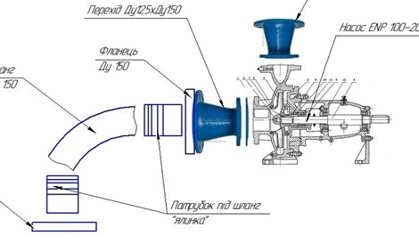
The image below shows a typical setup of a drip irrigation pump that draws water from a river, below the pump installation level.
The height difference between the water surface and the pump axis is small – only 1.5–2 m – but the suction pipe length is about 5 m. Therefore, a pump with a DN125 suction port should be connected with a larger pipe – at least DN150.
July 11, 2025
Flow control of a positive displacement pump
Positive displacement pumps are devices that operate based on the principle of changing the volume of a working chamber. This can occur due to an eccentrically mounted impeller (in an impeller pump ), rotation of gears , piston movement, membrane movement , change in hose volume ( peristaltic pump ), etc.
Given the operating principle of such a pump, it can be concluded that regulating its performance with shut-off valves (by closing valves on the discharge or suction line) may be harmful and dangerous both to the pump and the system in which it operates.
Unlike dynamic pumps, these pumps do not generate pressure but are capable of overcoming certain pressure, which may reach dozens or even hundreds of megapascals (MPa).
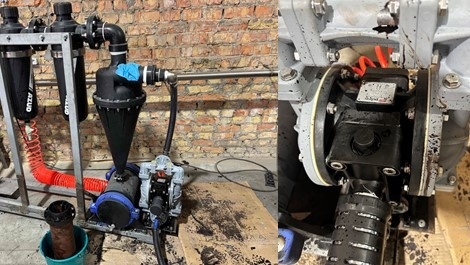
This means that if, for example, a gear pump is operating in a circulation system, the pressure gauge will actually show the resistance of the piping system (pipes, bends, filters).
Pressure gauge in a transformer cooling system. A gear pump ENP 1010 is operating with a maximum pressure of 15 bar. The pressure gauge shows 0.2 bar.
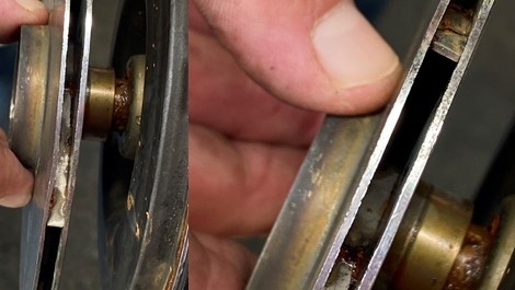
Below in the photo – the result of closing the valve on the discharge pipe in the same system.
As a result of closing the valve, the sealing rubber was damaged.
Another example – an attempt to regulate flow with a valve in an impeller pump AlphaDynamic .
As a result – damage to the impeller and the need for repair.
Conclusion – the operation of a positive displacement pump should be regulated using a bypass line or frequency inverter. IT IS STRICTLY FORBIDDEN to close shut-off valves at the pump inlet or outlet. If a bypass line is not installed in the system, safety valves must be used.
July 3, 2025
Peculiarities of wet rotor pumps operation
Wet rotor pumps are a large group of pumps widely used in heating and cooling systems.
Thanks to their silent operation, low energy consumption, and absence of mechanical seals, they occupy a significant niche both in industrial systems and residential heating installations.
Currently, you can purchase basic options like single-speed pumps without any control, as well as “smart” electronic pumps with pressure and flow control and multiple operating modes.
Despite all the advantages listed above, these pumps have one significant drawback — the quality of the water or heat carrier they work with. Regardless of the level of smart electronics involved, the core element of this type of pump equipment remains the mechanical part — the "wet rotor".
Since the rotor is washed by the pumped medium, its quality must be adequate — clean, and free from mechanical impurities (scale, sand, rust flakes, etc.).
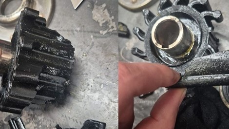
The photo below shows a pump that was sent to us for servicing due to rotor jamming after just 1.5 months of operation.
The impeller and the gap between the rotor and stator were clogged with rust flakes, which caused the rotor to seize.
Conclusion — when using pumps of this type, it is crucial to ensure proper water treatment. With clean water, the pump will last well beyond the warranty period.
Otherwise, you should consider pump systems that are less sensitive to water quality — such as inline dry rotor pumps equipped with a standard asynchronous motor and mechanical seal.