Installation of a thermal oil circulation pump and piping
 Administrator 1November 5, 2025
Since this pumping equipment operates with a heat transfer medium based on thermal oil at high temperatures (from 130 to 350 °C), pump installation, motor connection, electrical wiring, and pipeline assembly may only be performed by qualified personnel.
The following rules must be observed during pump installation:
- Remove protective covers from the flanges.
- The pump must be installed in locations free from the risk of freezing or explosion and where good ventilation is ensured.
- There must be sufficient space around the pump to allow convenient installation and maintenance.
- The suction pipe should be as short as possible.
- The pump assembly must be placed on a steel support frame and securely fastened using bolted connections. The frame structure must be rigid enough to prevent vibration during operation and must also allow adjustment of the motor position relative to the pump.
The support frame should be mounted on a horizontal concrete base using anchor bolts or by welding to embedded steel elements.
Pump installation
- The pump may only be installed in a horizontal shaft position.
- Pumps up to 5–10 kW are installed on a metal frame, while more powerful pumps require a foundation. The concrete foundation must weigh at least twice as much as the pump with the motor. The length and width of the foundation should exceed the frame dimensions by 100 mm on each side. If necessary, vibration isolation should be used for high-power pumps.
- The pump casing is mounted on the frame or foundation with bolts through the mounting foot holes.
- For proper cooling of the motor, the distance from the nearest structure must be at least 0.5 m.
- During thermal insulation, only the pump casing (volute) and the connection nozzles may be insulated. Insulating the motor is strictly prohibited.
- Before installation, ensure that the shaft rotates freely by turning it via the coupling after removing the cover.
- Before connecting the pump, flush the pipelines to remove scale, slag, and other contaminants.
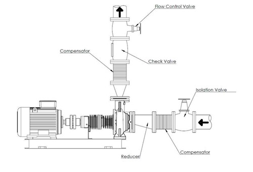
Connection to the pipeline
- The working medium enters through the axial inlet and exits through the radial outlet of the centrifugal pump.
- The diameters of the inlet and outlet pipelines are selected based on calculations and are usually 1–2 nominal sizes larger than the pump nozzles.
- The pump casing must not be subjected to twisting, stretching, bending, or compression caused by the connected pipelines. For maintenance, shutoff valves must be installed before and after the pump. The shutoff section must include a drain valve.
- To protect the pump from damage by solid particles, install a mesh strainer before the pump.
- To eliminate vibration transfer to the connected pipelines, use anti-vibration connectors on the suction and discharge lines.
- In multi-pump parallel installations, a check valve must be installed on the discharge side of each pump.
- For flanged joints, place a washer between the nut/bolt head and the flange.
- The pipeline flanges must be parallel to the pump flanges, with gaskets suitable for the parameters of the pumped medium.
- Install pressure gauges before and after the pump to monitor operation.
- The pump must not be used as a support point or structural element for the pipeline.
- Pipelines must be supported as close to the pump as possible. Ensure that the weight, stress, or deformation of the pipeline is not transferred to the pump.
- Excessive pipeline stress can cause leakage of the working medium.
- The nominal nozzle dimensions do not determine the pipe diameter selection. The pipe diameter must be equal to or larger than the nozzle diameter. Using pipes or fittings of smaller diameter is prohibited.
- Connections must be made with flanges and appropriately sized gaskets of suitable material. The gasket must be centered so as not to restrict flow.
- Thermal expansion and vibration of the pipelines must be compensated using vibration dampers and axial compensators to prevent additional loads.
- The suction pipe must not contain air pockets, so it should slope slightly toward the pump.
- The suction-side gate valve must be installed as close to the pump as possible; during operation it must be fully open and must not be used for flow regulation.
- The discharge-side gate valve must be installed as close to the pump as possible to regulate flow during pump startup.
Additional pipeline connections and accessories
- To monitor pump operation, install pressure gauges and thermometers on the pipeline. For automation — temperature and pressure sensors.
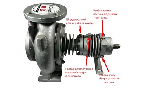
- Each pump has threaded ports for connecting relief lines to the oil chamber. The oil chamber can be connected to a drain tank to allow oil removal in case of leakage. The connection must be made through a safety valve with a pressure rating equal to the pump’s maximum pressure.
Bypass installation
If the pump may operate for a long period with the discharge valve closed or with very low flow, a bypass line must be installed to return the medium to the suction line and prevent the pump from overheating.
The bypass line should connect the discharge pipe to the suction pipe.
On the discharge pipe, the bypass is connected between the pump discharge nozzle and the valve, with an overflow valve installed.