2025 — Prom-nasos.com.ua
November 7, 2025
Operation of a centrifugal pump under vacuum
First, a bit of theory.
NPSH — “Net Positive Suction Head,” also known as the cavitation margin — is the most important parameter for evaluating a pump’s suction capability. NPSH defines the minimum pressure at the pump inlet required for cavitation-free operation.
There are two NPSH values: NPSHr (“required”) — the required cavitation margin, i.e., the minimum pressure needed at the pump suction nozzle. NPSHr for each pump is determined through factory testing and indicated on graphs and in tables (see Fig. 1). Note that these data are provided for liquid temperature of +20°C.
Fig. 1
Comparison of NPSH values for pumps operating at 1500 and 3000 rpm.
NPSHa (“available”) — the available suction head in the system where the pump is installed. Since pumps operate within a system ( heating, water supply, wastewater , alcohol production , food processing, etc.), pump performance depends largely on the piping layout, the system configuration, shut-off valves , automation , and not only on the pump's construction or manufacturer.
NPSHa (system) must always be greater than NPSHr (pump)
NPSHa > NPSHr
This condition must be met for proper, cavitation-free pump operation.
Let us consider an example of pump operation when pumping liquid from a vessel under vacuum. This could be, for example, a chemical reactor or a distillation/fermentation column , from which stillage is being removed.
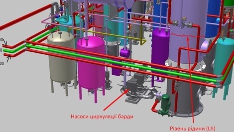
The basic scheme of such a process is shown in Fig. 2
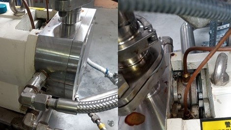
The engineering design is shown in Fig. 3
Fig. 2
Fig. 3
NPSHa for a system operating under vacuum is calculated using the following formula:
NPSHa = P + Lh − (Vp + Hf)
P — pressure above the liquid surface in a closed vessel (gauge pressure);
since the vessel is under vacuum, we assume P = 0 (absolute vacuum, although in real systems absolute pressure will never be exactly zero)
Lh — maximum static head (flooded suction height);
Vp — vapor pressure of the liquid at the maximum operating temperature;
Hf — friction losses in the suction pipeline at the required pump flow rate;
From this formula, we can conclude that to increase the pump’s suction capability, one must increase the liquid column height (Lh), reduce the vapor pressure (Vp) — since it depends on temperature, cooler liquid is preferable — and reduce friction losses in the pipeline (increase suction pipe diameter, install shut-off valves of larger diameter).
As shown in Fig. 1, it is preferable to use pumps operating at 1500 rpm instead of 3000 rpm.

November 6, 2025
Choosing a battery for an inverter and UPS
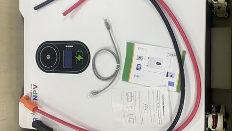
Our company specializes in selling batteries of various voltages from manufacturers ROSEN and Cooli .
The batteries are compatible with hybrid inverters and/or uninterruptible power supplies (UPS) from 12 to 24 V – “low-voltage” – and 44–56 V (“high-voltage”).
We would like to note that when choosing LiFePO4 batteries, there are several important nuances:
It is important (!) to know the specifications of the inverter or UPS to which the LiFePO4 battery will be connected.
The voltage of the average expected energy consumption.
The amount of time during the day for which the batteries must provide power.
We will select a battery from a certified manufacturer
November 5, 2025
Installation of a thermal oil circulation pump and piping
Since this pumping equipment operates with a heat transfer medium based on thermal oil at high temperatures (from 130 to 350 °C), pump installation, motor connection, electrical wiring, and pipeline assembly may only be performed by qualified personnel.
The following rules must be observed during pump installation:
Remove protective covers from the flanges.
The pump must be installed in locations free from the risk of freezing or explosion and where good ventilation is ensured.
There must be sufficient space around the pump to allow convenient installation and maintenance.
The suction pipe should be as short as possible.
The pump assembly must be placed on a steel support frame and securely fastened using bolted connections. The frame structure must be rigid enough to prevent vibration during operation and must also allow adjustment of the motor position relative to the pump.
The support frame should be mounted on a horizontal concrete base using anchor bolts or by welding to embedded steel elements.
Pump installation
The pump may only be installed in a horizontal shaft position.
Pumps up to 5–10 kW are installed on a metal frame, while more powerful pumps require a foundation. The concrete foundation must weigh at least twice as much as the pump with the motor. The length and width of the foundation should exceed the frame dimensions by 100 mm on each side. If necessary, vibration isolation should be used for high-power pumps.
The pump casing is mounted on the frame or foundation with bolts through the mounting foot holes.
For proper cooling of the motor, the distance from the nearest structure must be at least 0.5 m.
During thermal insulation, only the pump casing (volute) and the connection nozzles may be insulated. Insulating the motor is strictly prohibited.
Before installation, ensure that the shaft rotates freely by turning it via the coupling after removing the cover.
Before connecting the pump, flush the pipelines to remove scale, slag, and other contaminants.
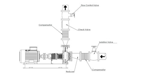
Connection to the pipeline
The working medium enters through the axial inlet and exits through the radial outlet of the centrifugal pump.
The diameters of the inlet and outlet pipelines are selected based on calculations and are usually 1–2 nominal sizes larger than the pump nozzles.
The pump casing must not be subjected to twisting, stretching, bending, or compression caused by the connected pipelines. For maintenance, shutoff valves must be installed before and after the pump. The shutoff section must include a drain valve.
To protect the pump from damage by solid particles, install a mesh strainer before the pump.
To eliminate vibration transfer to the connected pipelines, use anti-vibration connectors on the suction and discharge lines.
In multi-pump parallel installations, a check valve must be installed on the discharge side of each pump.
For flanged joints, place a washer between the nut/bolt head and the flange.
The pipeline flanges must be parallel to the pump flanges, with gaskets suitable for the parameters of the pumped medium.
Install pressure gauges before and after the pump to monitor operation.
The pump must not be used as a support point or structural element for the pipeline.
Pipelines must be supported as close to the pump as possible. Ensure that the weight, stress, or deformation of the pipeline is not transferred to the pump.
Excessive pipeline stress can cause leakage of the working medium.
The nominal nozzle dimensions do not determine the pipe diameter selection. The pipe diameter must be equal to or larger than the nozzle diameter. Using pipes or fittings of smaller diameter is prohibited.
Connections must be made with flanges and appropriately sized gaskets of suitable material. The gasket must be centered so as not to restrict flow.
Thermal expansion and vibration of the pipelines must be compensated using vibration dampers and axial compensators to prevent additional loads.
The suction pipe must not contain air pockets, so it should slope slightly toward the pump.
The suction-side gate valve must be installed as close to the pump as possible; during operation it must be fully open and must not be used for flow regulation.
The discharge-side gate valve must be installed as close to the pump as possible to regulate flow during pump startup.
Additional pipeline connections and accessories
To monitor pump operation, install pressure gauges and thermometers on the pipeline. For automation — temperature and pressure sensors.
Each pump has threaded ports for connecting relief lines to the oil chamber. The oil chamber can be connected to a drain tank to allow oil removal in case of leakage. The connection must be made through a safety valve with a pressure rating equal to the pump’s maximum pressure.
Bypass installation
If the pump may operate for a long period with the discharge valve closed or with very low flow, a bypass line must be installed to return the medium to the suction line and prevent the pump from overheating.
The bypass line should connect the discharge pipe to the suction pipe.
On the discharge pipe, the bypass is connected between the pump discharge nozzle and the valve, with an overflow valve installed.
November 4, 2025
Sealed pumps for liquefied gases, chemically active liquids
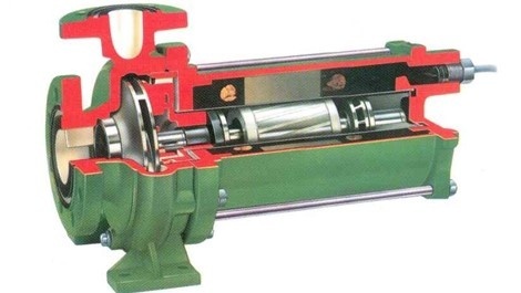
Hermetic pumps are a special group of pumps designed for specific applications. This equipment is used for transferring particularly hazardous substances, such as liquefied ammonia, nitrogen, aggressive acids, and toxic materials.
Pumps of this type have no seals on rotating parts; their working chamber is completely hermetic, eliminating the possibility of leakage.
Technical specifications of the seal-less hermetic motor pump:
Capacity: Q up to 1200 m³/h.
Head: H up to 800 m.
Liquid temperature range: from -200 to 450°C.
Material: Metal: SS304/316/316L; Hastelloy C4, C276, etc.; Insulation: H, C, Super-C, etc.
Gasket: PTFE, metal spiral wound gasket, etc.
Flange standards: ANSI, ASME, HG, DIN, JIS, GB, SH.
Standard explosion-proof terminal box: Exd IIC T1-4, Exd IIB T1-4.
High-efficiency design with anti-cavitation characteristics.
Automatic axial balancing.
Seal-less hermetic motor pumps are used in the oil, chemical, medical, textile, and nuclear power industries, as well as in defense, shipbuilding, municipal water supply and wastewater systems, high-pressure firefighting systems, and high-rise building water supply applications.
November 3, 2025
Operation of a gear pump
Gear pumps are positive displacement pumps that offer a number of significant advantages:
they can pump high-viscosity products;
they have the ability for “dry priming,” meaning they do not require pre-filling of the working chamber;
the pumping process is smooth, with a stable laminar flow;
the possibility of reverse operation;
easy and precise flow regulation using frequency converters or mechanical gearboxes and variators.
Despite these excellent features, there are of course certain precautions that must be taken into account when operating a gear pump:
The liquids being pumped must have lubricating properties (fats, glycerin, oil, motor lubricant, etc.). A gear pump must not be used to pump, for example, water, gasoline, solvent, or liquids containing solid particles. This can lead to the gears jamming and the motor windings burning out.
The liquid should not contain hard abrasive or chemically active substances that can damage the working components — in particular the gears and the pump chamber. The design of a gear pump is based on minimal but sufficient clearances between the gears and the mating parts, which ensures high hydraulic efficiency and the advantages mentioned above;
The pipeline or the pump itself must be equipped with a safety valve or bypass to prevent damage in case the valve on the discharge line is accidentally closed.
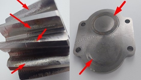
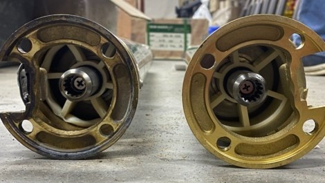
The photos below show a typical example of gear pump operation in which sugar syrup containing undissolved sugar crystals was pumped.
The photos clearly show wear on the cover, the end face of the gear, and the gear teeth caused by the mechanical impact of solid particles.
Conclusion — before operation, read the user manual, remember the important points described there, and follow the instructions — this will significantly extend the service life of your pump.
November 1, 2025
Features of the WQK line
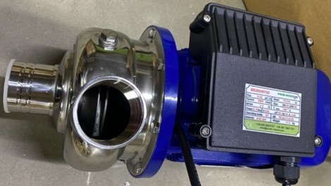
WQK series pumps are specially designed for pumping sewage, drainage, and industrial wastewater containing impurities.
The design includes:
a specially designed impeller with a cutting edge that easily handles solid and long-fibred inclusions;
high wear resistance thanks to durable materials used for the pump body and impeller;
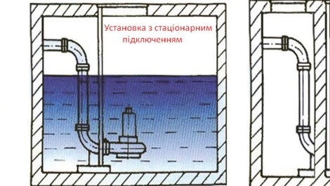
easy installation — the pump can be mounted either stationary or in mobile systems;
the delivery set includes a 90° flanged elbow for a hose, complete with a clamp and fastening hardware.
The WQK 35-10-3 model is suitable for medium-volume tasks: pumping sewage, technical liquids, or rainwater.
Where it is used:
Municipal utilities — sewage systems of private houses and multi-storey buildings.
Industrial facilities — pumping technological wastewater and dirty water.
Agriculture — field drainage, pond drainage, water intake from open reservoirs.
Construction — removal of groundwater and rainwater on construction sites.
Operating notes and recommendations
Before starting, the pump must be fully submerged in water to avoid “dry running”.
It is recommended to install an overload protection relay, as the motor may overheat if the impeller becomes jammed.
For long service life, periodically check the condition of the cutting mechanism and seals.
If the pump is used in a system with a high content of solid particles, it is advisable to install filter grates before the intake.
WQK 35-10-3 is a drainage pump designed for those who need a reliable solution for handling dirty water. It combines durability, easy maintenance, and versatility of use. This unit is a good investment both for private households and industrial applications, as it allows quick and trouble-free water removal.
You can order this pump or select a model according to your needs via this link .
October 20, 2025
Centrifugal pumps BB
Purpose
The main task of this pump is to transfer liquids with a stable flow and without pulsations. The pump is perfectly suited for operation in both industrial and municipal systems. In particular, it is used for:
supplying water in water supply systems;
circulating liquids in cooling and heating systems;
supporting technological processes in food, chemical, and light industry enterprises;
irrigation in agriculture.
Application area
The BB centrifugal pump is installed in boiler houses and heating units, production workshops, agricultural complexes, centralized and local water supply systems, the food industry (for example, for washing vegetables and fruits on production lines), for supplying cooling water to equipment, for transferring process solutions (such as saline or sugar solutions), in chemical and pharmaceutical industries, for pumping glycol-water solutions (in cooling systems), for feeding reagents in production processes, and for circulating neutral or slightly acidic liquids.
Advantages of the model BB250/075D
Reliability – the simple design minimizes the risk of breakdowns.
High performance – the pump can deliver large volumes of liquid at stable pressure.
Energy efficiency – the optimized motor operation helps save electricity.
Versatility – suitable for various applications, from municipal services to industrial facilities.
Easy maintenance – free access to working parts simplifies servicing and repair.
Thanks to its ability to handle various types of liquids — from drinking water to technical solutions — the BB250/075D pump is a convenient solution for industrial operators, farmers, and municipal utilities alike.
Submersible pumps of the 4SD 6/23-2.2 380V series are reliable and efficient units used for supplying clean water from medium and deep wells. However, even with proper operation, over time there may arise a need to replace the pump section. This is a normal process of wear of the impellers and hydraulic components, as the pump operates daily under load in a water environment.
Signs that the pump section has failed:
significant drop in performance (the water flow becomes weaker);
the pump takes longer to reach operating mode;
unusual noises or vibrations are heard during operation;
the water becomes cloudy due to excessive friction between parts.
If the motor is in good condition during diagnostics and the issue lies only in the hydraulics, replacing the pump section is the most economical and correct solution.
How the replacement process works:
Removing the pump from the well.
Disconnecting the electric motor. Before disassembly, always make sure there is no voltage.
Removing the worn pump section. The old impellers and diffusers are replaced with new factory-made components.
Installing the new pump section and connecting it to the motor.
Inspection and test run. The pump is started in a water tank before being lowered into the well.
Proper operation after replacement
Always check the water quality. If the well contains a lot of sand, it is recommended to install a filter or case the lower section.
Do not allow “dry running.” Operating without water will damage the mechanical seal .
Monitor the power supply. The voltage should remain stable at 380 V ±5%. In case of phase imbalance, the motor may overheat and damage the hydraulic system.
Perform regular maintenance. Once a year, it is advisable to check the cable, couplings, suspension condition, and automation performance.
Replacing the pump section in the 4SD 6/23-2.2 380V model allows you to fully restore the pump’s performance without purchasing new equipment. Proper installation and adherence to operating conditions ensure stable operation of the unit for many years.
September 10, 2025
Lobe pumps for viscous products
Lobe pumps (rotary, vane, flap) with a steam jacket are a type of pumping equipment specially designed for products that tend to solidify or crystallize quickly when the temperature drops.
The pump design incorporates the “steam jacket” method, which includes two types: the pump body or the pump cover. Steam or hot water can be supplied to the body or cover of the pump to maintain a constant temperature of the working chamber. This effectively prevents seal damage caused by material solidification during start-up.
The steam jacket can be widely used for products whose viscosity is highly affected by temperature. These pumps can be used in the production of sugar, chocolate, pharmaceuticals, butter, and more.
Lobe pump for pumping caramel at 140°C
Applications:
The rotary food pump can be used to transport all kinds of materials with medium and high viscosity as well as high solid content.
Lobe pumps are widely used in the production of sugar, chocolate, dairy products, various syrups, concentrated fruit juice, jelly, yogurt, honey, ice cream, cake fillings, cereal porridge, soy protein, meat fillings, seasonings, tomato paste, caramel, bean paste, and other products.
September 5, 2025
Replacement of Wilo MHI series pumps with Medana series pumps
A well-known German manufacturer of pumping equipment, Wilo (Dortmund, Germany), whose official representative is our company, has discontinued the popular in Ukraine horizontal multistage pumps of the MHI series due to the release of new, more energy-efficient pumps.
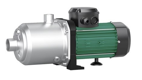
Pump of the MHI series
Despite their external appearance (the pumps look almost identical).
Pump of the Medana series
The Medana series pumps are equipped with a more energy-efficient electric motor and an improved hydraulic section.
As before, by purchasing pumps from this manufacturer, you get high quality at an affordable price.
Pumps of this series are characterized by high hydraulic efficiency, reliability, and maintainability.