News Prom-nasos
Fields of application
Chemical industry
Paint and coatings production
Oil and gas as well as petroleum refining
Pharmaceuticals and biotechnology
Explosion-hazardous production facilities
Laboratories working with hazardous substances
This pump works well with liquids that aggressively affect metals, have high volatility or toxicity, and where emulsions, suspensions, or solid particles in the composition are common.
Advantages
Full explosion protection
Thanks to ATEX certification, the pump operates without the risk of sparking, which is extremely important when working in hazardous conditions.
Corrosion-resistant materials
Polypropylene and PTFE withstand aggressive chemical environments, as well as acidic or alkaline solutions.
No electric drive
Pneumatic operation eliminates the need for electricity.
Easy maintenance
The simple diaphragm-type design allows for quick and convenient technical servicing.
Flexible use
Suitable for a wide range of liquids: from clean to viscous, abrasive, or chemically active.
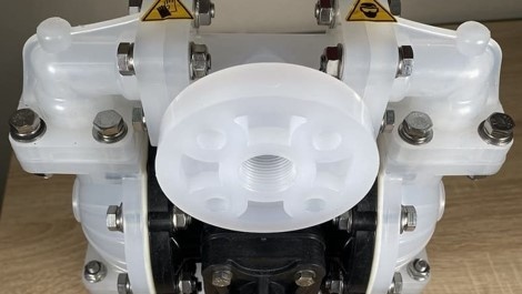
ATEX DiaPump DP 05 PP/T is a reliable option that can be used without issues for pumping aggressive, explosive, and complex liquids in industrial conditions. The combination of the explosion-proof ATEX standard, corrosion-resistant materials, and easy maintenance makes this pump suitable for various industries.
The pump is designed to operate for a long time and ensure personnel safety.
You can order the ATEX DiaPump DP 05 PP/T pump on our website — simply add it to the cart or contact our consultants.

March 13, 2026
Molecular sieve type 3A

Molecular sieve type 3A is a type of zeolite with very small pores approximately 3 angstroms (0.3 nm) in diameter. Due to its properties, it can adsorb small-sized molecules, making it highly effective for selective adsorption.
For example:
Water (H₂O) — the main application: drying of gases and liquids;
Ammonia (NH₃);
Methanol (CH₃OH).
At the same time, larger molecules such as ethanol (C₂H₅OH), butane, or long-chain hydrocarbons cannot enter the pores and therefore are not adsorbed.
Main applications of 3A molecular sieve:
Drying of natural gas and biogas — removes water vapor without adsorbing larger molecules (e.g., hydrocarbons).
Drying of hydrogen, oxygen, nitrogen, and helium — often used in industrial installations to achieve extremely low moisture levels.
Used for drying ethanol, methanol, and other alcohols — allows achieving a high degree of dehydration, for example in the production of anhydrous ethanol.
Removal of water from liquefied petroleum gas (LPG), propane, and butane.
Used during storage and transportation of hydrocarbons to prevent corrosion and hydrate formation.
As an adsorbent in packaging to maintain a dry environment.
Used in product concentration or purification processes.
March 12, 2026
Impeller pump
Impeller pump belongs to vane rotary pumps and is a positive displacement pump. It is referred to in different ways: a flexible vane pump, a soft rotor pump, or a flexible impeller pump. However, all these names refer to the same type of pump — the impeller pump.
Fields of application: food industry, cosmetics industry, chemical industry, and pharmaceutical industry.
The pump is used for pumping thick and viscous products such as honey, jam, yogurt, preserves, condensed milk, etc.
In the cosmetics industry, it is used for pumping shampoos, face masks, gels, creams, and lotions.
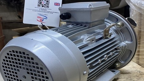
The impeller pump consists of two main parts: the electric motor and the pump housing.
The pump uses a closed-type asynchronous electric motor with a maximum shaft rotation speed of up to 1,500 revolutions per minute. Most commonly, pumps with an electric motor operating at 900 rpm are used. The power range of electric motors for impeller pumps varies from 0.55 kW to 6 kW. Pumps are available both with and without a motor.
The pump housing consists of a front cover, a rear cover, a flexible impeller, a mechanical seal, and a mounting flange.
The moving part of the pump — the impeller — is located inside the housing and positioned between the front and rear covers. It is a wide, monolithic open-type impeller with a varying number of flexible blades. The width of the impeller affects the pump capacity. The flexible impeller pump is self-priming and can lift the product from a depth of up to 5 meters.
The impeller pump combines the capabilities of a centrifugal pump and a positive displacement pump: it creates pressure and flow while also being able to pump thick and viscous liquids.
A wide range of impeller pumps from the well-known manufacturer AlphaDynamic can be purchased in our online store.
March 11, 2026
NOVAX series pumps from Italian manufacturer ROVER POMPE

NOVAX series pumps from the Italian manufacturer ROVER POMPE are designed for pumping any type of liquid that is not chemically aggressive or abrasive.
These pumps are widely used in the food, pharmaceutical, and cosmetic industries.
ROVER POMPE specializes in liquid ring (vortex) and gear pumps.
Pumps of this series are made from a high-quality stainless steel alloy specially developed to ensure resistance to corrosion and chemical effects, providing high quality and reliability.
Applications: pumping water, wine, milk, whey, beer, wort, mash, syrup, emulsions, vinegar, low-viscosity oil solutions, and neutral liquid detergents.
March 10, 2026
Active dry yeast
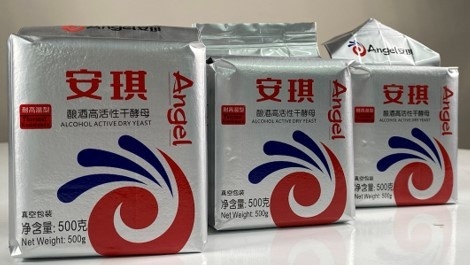
Angel Thermal Tolerance Alcohol Active Dry Yeast is an active dry alcohol yeast specially developed for fermentation under conditions of high temperature, high alcohol content, and acidity. The yeast is suitable for the production of fuel and food-grade ethanol from raw materials such as corn, rice, cassava, sorghum, as well as sugar-containing raw materials.
Main characteristics:
Temperature resistance: the yeast can operate at high temperatures (from 28 °C to 42 °C).
Ethanol tolerance: up to 17% vol. (v/v).
Acid resistance: capable of fermenting at pH up to 2.5, which helps prevent bacterial contamination and increases ethanol yield.
Osmotic resistance: withstands up to 60% glucose.
Moisture content: not more than 6.5%.
Live yeast cells: not less than 75%.
Total yeast count: not less than 2.5 × 10⁹ /g.
Application: add dry yeast to the fermentation vessel at a rate of 2.5–3 kg of yeast per 1 m³ of wort. The initial number of yeast cells in the wort reaches 5 million/ml.
March 9, 2026
Compact sewage pumping stations
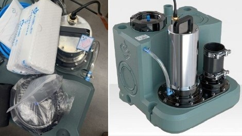
AIZL sewage pumping station is a ready-made solution both for a private house and for an industrial facility (bomb shelters, basement premises, cottages, wastewater drainage from food industry enterprises, etc.).
Advantages of a compact modular sewage pumping station
complete tightness, no odor;
plastic tank of various volumes depending on capacity, resistant to corrosion in aggressive environments;
external electric motor with oil cooling made of stainless steel — reliable operation and easy maintenance;
electronic water level sensor — accurate measurement and timely switching on and off of the pump;
remote control panel with a touchscreen is included in the set;
can be used with water temperatures up to +60℃, short-term up to +90℃.
Such a pumping station is a ready-made solution for sewage systems. The assortment includes stations for private houses as well as models for industrial use with the PRO designation.
March 5, 2026
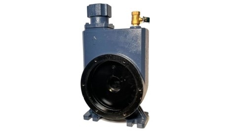
Self-priming dirty water pumps as an alternative to submersible drainage and sewage pumps
Submersible drainage and sewage pumps are undoubtedly very widely used both in industry and in the private sector.
The main disadvantage of this type of pump is the complexity of maintenance and repair. If the mechanical seal fails or the motor burns out, the pump has to be removed from the septic tank, washed, and the pumping part must be disassembled. Often, due to the long-term presence of the equipment in an aggressive environment, even a simple operation such as unscrewing the mounting bolts becomes a difficult task.
An alternative solution to these pumps is self-priming pumps for dirty water designed for surface installation.
Due to the presence of a priming chamber (see the photo below)
and a special impeller design – a vortex, multi-channel impeller (see the photo below).
These pumps can be successfully used for pumping surface water from septic tanks and cesspits.
The advantage of using such a pump is the possibility of applying it for pumping liquid from tanks with a narrow neck, when it is not possible to install a sewage pump, since in this case it is enough to lower only a pipe into the septic tank.
In addition, this pumping equipment is convenient to maintain. For example, the replacement of the mechanical seal can be performed on site, even without dismantling the pump from its installation location.
March 4, 2026
The working principle of a cam pump
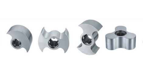
Lobe pump – a positive displacement pump. The product is transferred by means of lobes between the walls of the working chamber and the lobes.
The lobes can have different shapes depending on the pumped product, its density, and viscosity.
Features of the lobe pump:
during rotation, the lobes do not come into contact
Unlike a gear pump , where the driving gear transmits torque to the driven gear through direct contact, a minimal clearance is always maintained between the lobes and the casing.
Thanks to this feature, the pump operates quietly, and the pumping process is smooth without damaging the product.
the lobe pump operates at low speeds – from 200 to 500 rpm.
The low operating speed ensures no pulsation, does not foam the product (detergents, dairy products, various types of oils), and significantly increases the service life of bearings and mechanical seals.
can pump hot products at temperatures up to 150℃
Thanks to the special design of the mechanical seal , as well as its placement outside the working chamber, this type of pump can handle hot products with various inclusions.
March 3, 2026
Determining the volume/mass of bulk fillings
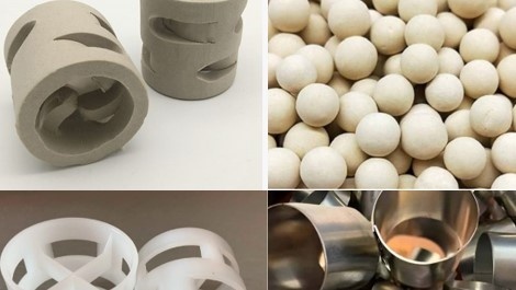
Our company has been successfully supplying random column packing of various types made from different materials for many years. In particular, these include Pall rings, Raschig rings, molecular sieves, ceramic balls, etc.
Each of these types of packing is used in various technological processes such as purification, dehydration, saturation, improvement of mass transfer, and many other processes.
The vast majority of this product is accounted for in kg (kilograms) and is accordingly shipped to the customer in kilograms. The price of the product is also indicated per 1 kg.
Customers often ask how many kilograms of a particular product need to be purchased in order to fill a given volume of a column or tank.
For bulk products, a characteristic called bulk density is used.
Bulk density is the ratio of the mass of the packing to the volume it occupies. It is measured in kg/m³.
This characteristic is indicated in the product card for each product (see the photo above). Accordingly, as follows from the formula, to determine the required mass of the packing, it is necessary to multiply the bulk density by the specified volume.
For example, you need to calculate the required mass of Raschig rings A1 25 according to GOST 17612-89 to fill a column with a volume of 2.3 m³.
Accordingly, the required mass of the packing m = 2.3 × 596 = 1370.8 kg
You can also solve the reverse problem — calculate what volume can be filled with a certain amount of packing.
If you have, for example, 200 kg of packing from the previous example, then you can fill a volume V = 200 / 596 = 0.336 m³, that is 336 liters.
February 25, 2026
Asphalt production. Dosing of additives to bitumen
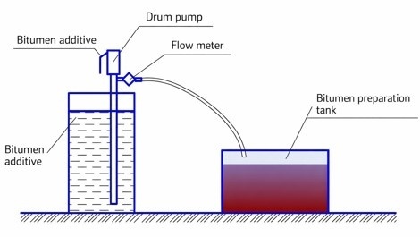
When preparing bitumen mixtures used for asphalt production, it is necessary to dose special additives into the bitumen.
A single dose of the additive can range from 20 to 80 liters depending on the concentration of the additive and the grade of bitumen.
For small-scale production, this task can be handled by a drum pump using a flow meter.
or a measuring container (a cheaper option)
For large enterprises, a dosing scheme can be implemented based on stainless steel vortex pumps by ROVER or gear pumps from the WCB series .
Using a flow meter with a control signal, the pump will automatically shut off after a specific volume has been dispensed.
Or using the same pumps in combination with a timer relay.