News Prom-nasos
May 18, 2026
AISI 304 Stainless Steel Butterfly Valves
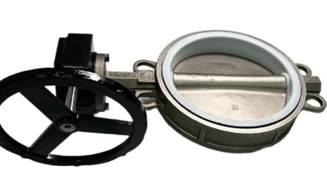
AISI 304 stainless steel butterfly valves are currently quite frequently ordered for water, various technical liquids, and industrial systems. Mainly because stainless steel handles moisture well and does not start rusting after a short period of time, as is often the case with cheaper alternatives.
In this model, both the body and the disc are made of AISI 304, while the seal is made of PTFE. In practice, this means the valve provides tight shut-off and operates reliably in the system without constant intervention or maintenance. This is important for many users, especially when equipment operates daily.
The advantage of a large-diameter butterfly valve with a worm gear reducer is the ability to operate it manually without significant physical effort, ensuring smooth opening and closing.
Most commonly used in:
pump stations;
irrigation systems;
fire protection systems;
main water supply pipelines;
wastewater treatment plants;
industrial pipelines.
There is nothing complicated about installation. The design is compact, which is why butterfly valves of this type are often installed where space is limited or where other equipment is already in place. The mechanism itself is simple and opens easily without unnecessary effort.
These butterfly valves can be found in industrial production, water supply systems, and even in some food processing applications. Everything depends on the medium and temperature conditions for which the valve is selected.
These valves are currently in stock. We can also offer other diameters and models for various applications and pipeline types.

May 15, 2026
Methods for Installing Sewage Pumps
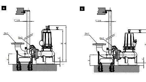
Proper installation is the key to efficient and reliable operation of the pump . Several main installation options are used for these pumps:
1. Stationary submersible installation
The most common option.
The pump is installed directly into a receiving tank (well or septic reservoir) and operates in a fully submerged condition.
Advantages:
stable operation;
efficient motor cooling;
minimal noise level;
long service life.
It is usually used together with automation systems (float switches), allowing the process to be fully automated.
2. Stationary installation with guide rails (rail system)
This makes it a more professional installation option.
The pump is lowered into the shaft along guide rails and automatically connected to the discharge pipe.
Advantages:
quick removal without descending into the well;
convenient maintenance;
personnel safety.
This is a good solution for hotels, residential complexes, and commercial facilities.
3. Mobile (temporary) installation
The pump is used as a portable unit — for example, for emergency pumping operations.
Advantages:
versatility;
the ability to quickly connect it wherever needed;
does not require complex installation.
It is especially relevant for service companies and construction work.
You can purchase the pump or get a free consultation simply by following this link .
In wastewater drainage systems, it is not always possible to organize a gravity sewer system. This is especially relevant for basements, temporary structures, hotels, or facilities operating under increased load conditions.
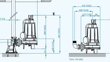
One of these models is the Dreno GRIX 32-2/140 T — a reliable pump that combines high performance, durability, and a cutting mechanism system.
Pump purpose
The Dreno GRIX 32-2/140 T is designed for pumping heavily contaminated wastewater, including:
sewage water;
domestic wastewater;
liquids containing various inclusions (wipes, paper, organic residues).
The key feature of this model is the grinding system, which allows solid particles to be shredded before entering the pressure pipeline. This is especially important when small-diameter pipes are used or when there is a risk of clogging.
Application areas
This pump does not have a narrow specialization — on the contrary, it is versatile and suitable for various facilities:
1. Private houses.
If a bathroom or kitchen is located below the level of the central sewer system, such a pump becomes essential for proper operation.
2. Bomb shelters and shelters.
Under autonomous conditions and in limited spaces, it is important to have a reliable wastewater removal system. A grinder pump helps prevent clogging even during intensive use.
3. Hotels and recreation centers.
Heavy sewer loads and varying wastewater composition require stable operation without frequent maintenance.
4. Commercial facilities.
Cafes, service stations, and car washes — places where wastewater often contains foreign particles.
5. Temporary or mobile structures.
Construction camps, portable cabins, and modular houses — locations without a stationary sewer system.
You can purchase this pump directly via this link .
May 12, 2026
Updates to the design of magnetic pumps
We would like to inform you about a minor design update of the QHX series magnetic pumps manufactured from PPH, PVDF, and CFRETE materials. The overall dimensions and connection sizes of the pumps remain unchanged, which will not create any issues for our customers when replacing the pump in the future. Details are provided below.
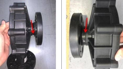
The QHX front cover has been upgraded from a “threaded + flanged design” to an integrated flanged structure manufactured by injection molding. Please find the update photos attached for reference. The inlet and outlet flanges have been upgraded from a bolted connection design to a one-piece molded structure, eliminating any risk of leakage at the flange connection points.
This update does not affect the performance or installation dimensions. It only improves sealing reliability and structural strength.
Conclusion: The purpose of this update is to optimize the product design, improve reliability, minimize the risk of leakage, and reduce maintenance costs.
Old flanged connection
New integrally injection-molded design
You can view or purchase these pumps using this link .
1. Installation location: The ambient temperature at the installation site should be 0–40 °C, and the relative humidity should be below 90%. Please choose a flat location where vibrations from other machines are not transmitted.
Leave sufficient space for maintenance.
2. Base fixation: The base area on which the pump is installed must be larger than the pump base itself. If the mounting area is too small, the pump may be damaged due to stress concentration at the contact point. The pump base must be securely fixed.
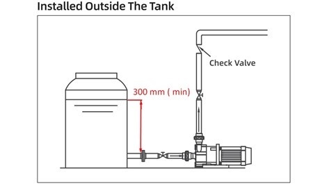
3. MD/QHX series pumps are NOT self-priming and must be installed under positive pressure conditions. The distance from the liquid surface to the suction inlet should be more than 30 cm. If the liquid head is too low, air may be drawn in, resulting in excessive wear of the pump bearings.
4. Pump discharge direction: The discharge outlet can be oriented freely, but to allow gas to escape from the pump chamber, it is recommended to direct the outlet upwards.
5. The pump head depends on the properties and temperature of the liquid, as well as the length of the suction pipeline. Keep the pipeline as short as possible and minimize the number of bends and turns.
6. Inlet and outlet valves should be installed as close as possible to the pump connections.
7. Check the voltage on the nameplate before connection. Proper grounding is mandatory.
8. The pump should be installed as close as possible to the tank and below its level (flooded suction installation).
Prohibited installation methods are shown in the figures below.
9. When the pump is used for handling hazardous liquids, flushing lines must be installed so that the internal parts of the pump can be cleaned after disassembly.
May 5, 2026
Protection of electrical equipment
The issue of electrical protection of equipment remains relevant at all times. Despite the vast amount of information on this topic and the wide range of protective devices, monitoring and control equipment, electric motors still fail.
Why does this happen? Most often, it is caused by the customer’s desire to save money on protection. Common justifications include statements such as: “Why do I need that control panel, everything works fine already,” “my old Soviet pump worked for 20 years without any problems,” “I turned it off because it keeps shutting down the pump and I have to go restart it,” and similar arguments.
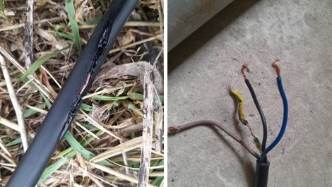
Here is an example of a typical “protection” setup for a 4 kW three-phase sewage pump.
And here is the result of such “protection”!
Another way to “burn out” your pump is to purchase a control box (protection and control panel) that supposedly has “everything included,” but fail to configure it according to your equipment parameters.
Every device, including pumping equipment and control panels, must be operated in accordance with the requirements specified in the operating manual.
As practice shows, the operating manual is often only read when there is nothing else left to read—or when everything has already burned out or seized.
Here is another example of a “warranty case.”
A borehole pump was connected through a protection and control panel , but no settings were configured.
The pump has a power rating of 4 kW, 380 V, and a nominal current of 8.8–9 A. Considering a permissible deviation of 10%, the protection current should be set to around 10 A.
However, the maximum protection current was set to 13.9 A.
And the no-load current was 8.5 A.
As a result, the pump was constantly shutting down during operation, since the no-load current was nearly equal to the nominal current, eventually leading to motor winding burnout.
Do not neglect the requirements of the operating manual! Contact our company’s specialists. We will help not only select the right equipment but also configure it correctly.
May 4, 2026
Adjusting the flow rate of a gear pump
Gear pump is a positive displacement pump. This means that the movement of the fluid (product) occurs due to a change in the volume of the working chamber.
Accordingly, the operating principle leads to the following conclusion — the flow rate of such a pump must not be regulated by closing shut-off valves on the discharge line.
When closing the valve on the discharge line, the following situations may occur:
damage to the gears
seal leakage
coupling damage
electric motor burnout
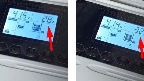
In the images below, you can observe the current consumption when the pump operates with an open line (left image) and when attempting to close the valve (right image).
When the valve is closed, the current immediately increases.
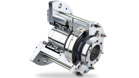
Cartridge seals are recommended for installation in pumps and mixers operating with such media as non-lubricating liquids, gases, liquids with a high concentration of solids, or those prone to crystallization, as well as adhesives, pastes, paints, and hazardous liquids.
Installation of cartridge mechanical seals:
Lubricate the shaft with a 2–3% aqueous solution of neutral liquid soap.
Slide the cartridge along the shaft until the flange contacts the housing.
Check the alignment of the seal on the shaft. Rotate the shaft by hand to detect any potential metal-to-metal noise. If the noise persists, check the shaft alignment.
Connect the appropriate lines for flushing, circulation, and barrier fluid.
This assembly requires a continuous supply of liquid, known as buffer or barrier fluid, into the chamber where the seal is installed. The pressure of the barrier fluid must be 0.5–2 bar higher than the pressure of the pumped (sealed) liquid. In case of seal failure, the barrier fluid will mix with the process liquid. This feature is especially important when the process liquid is hazardous or contaminating.
In a double cartridge seal, connect an external fluid for cooling the secondary seal.
In all cases, it is important to ensure that the process fluid contacts the seal before startup, as dry running can severely damage the sealing surfaces, even if it lasts only a short time. Although in some cases dry running cannot be avoided, special material combinations can be recommended to reduce its negative impact.
If the seal is located in the oil chamber of a pump filled with biodegradable petroleum jelly oil, this oil (lubricant) remains in the chamber continuously until the next service replacement. There is no pressure in the chamber itself.
In case of seal failure, the pumped liquid enters this chamber and mixes with the oil, which is detected by a water presence sensor (if installed).
An additional leakage chamber (motor chamber) on the motor winding side is usually empty. If pumped liquid enters this chamber, it may damage the electric motor.
April 20, 2026
Chemical pumps with magnetic couplings
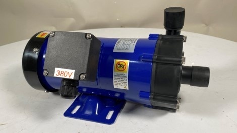
Chemical pumps with magnetic coupling are used for pumping aggressive substances, acids, alkalis, and solvents. Manufactured from high-quality materials resistant to corrosion and aggressive chemicals, they ensure high performance, reliability, and safety.
The operating principle of the pump is that the magnetic coupling transmits torque from the motor to the pump shaft through a magnetic field, eliminating any contact between the working parts. This reduces friction and wear of components, which extends the service life of the pump.
When selecting a pump, it is important to consider the needs of your production process, the nature of the working fluids, and other important parameters.
MD pumps from the manufacturer Qeehua have proven to be reliable.
To select the correct pump, it is necessary to know:
the substance that the pump will transfer;
capacity;
head (delivery height).
The material from which the pump is made depends on what exactly will be pumped.
For example: nitric acid (HNO3) 20%.
To select a pump, we review the compatibility table of pump materials with this acid. In Table 1 we can see that if the temperature of HNO3 is 40°C, GFRPP and CFRPP (types of polypropylene) are suitable. However, if the temperature is already 60–80°C, PVDF and CFRETFE should be used (a more chemically resistant version of PVDF).
Table 1
April 13, 2026
Cooling the electric motor of a well pump
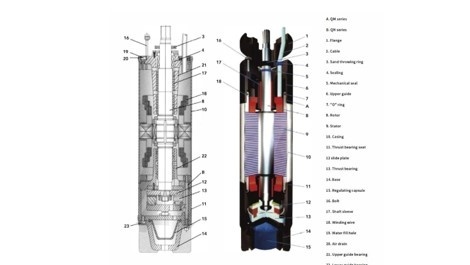
The electric motor of a borehole pump , unlike a standard asynchronous electric motor with air cooling, has certain features.
Due to the fact that it is located in a borehole, its diameter has certain limitations — it cannot be larger than the borehole itself. In addition, this motor is constantly under water, therefore it must be hermetically sealed.
Borehole pump motors are divided into two main groups:
oil-filled;
water-filled.
In the first case, the motor is filled with a special oil (lubricant), most often a petroleum jelly–based lubricant or another dielectric liquid that ensures its cooling.
Water-filled motors are cooled by water, while the winding wire of the electric motor is coated with PVC.
The tightness of the motor at the point where the drive shaft exits is ensured by a mechanical seal and additionally by a gland seal.
In both cases, cooling is provided by the water pumped by the pump. Water is drawn into the pump section at a certain velocity. The velocity depends on the pump capacity and the difference between the diameters of the motor and the borehole – (Dс-dн)
The detailed specifications of the borehole pump motor indicate the minimum water flow velocity along the motor housing required to ensure reliable cooling.
On average, the water velocity should be more than 8 cm per second. Therefore, as can be seen from the illustration above, when selecting a borehole pump it is necessary to consider the borehole diameter, pump capacity, and the diameter of the pump itself.
Our company’s managers are ready to help you choose a pump according to your needs!