News Prom-nasos
May 28, 2026
BZ Centrifugal Pumps
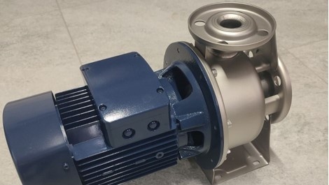
BZ centrifugal pumps can be used for pumping milk, whey, liquid fertilizers, UAN solutions, juices, CIP cleaning liquids, caustic soda, ammonia mixtures, wort, mash, wine, and many other liquids.
Pumps of this type operate according to the following principle: the liquid is captured by the impeller, which rotates and, under centrifugal force, moves the liquid from the center to the outer part of the casing. There, the velocity is converted into pressure, and the liquid is then delivered further through the pipeline.
Main pump components:
housing;
impeller;
shaft and motor;
inlet and outlet connections.
The pump is made of AISI 304 stainless steel.
Advantages of BZ centrifugal pumps: simple construction; high performance; smooth and continuous flow.
When handling milk, the pump provides gentle transfer without excessive agitation; does not damage the milk structure; supports CIP cleaning (automatic cleaning process).
When used for pumping beer, it ensures minimal foaming; gentle product transfer; preservation of CO₂.
These pumps do not operate well in dry-running conditions, are sensitive to air, and are less efficient when handling highly viscous liquids.

May 26, 2026
PHOENIX Pneumatic Diaphragm Pumps
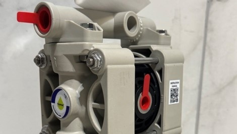
PHOENIX pneumatic diaphragm pumps from the Italian manufacturer FLUIMAC are used for pumping varnish, paint, nitric acid, ammonia, acetic and phosphoric acid, alkalis, ethylene, solvents, adhesives, and many other substances.
They operate using compressed air and two flexible diaphragms that alternately suction and discharge the liquid. One diaphragm bends and pushes the liquid out of the working chamber through the outlet valve. At the same time, the second diaphragm moves in the opposite direction, creating a vacuum — the liquid is drawn in through the inlet valve. The air valve automatically switches the air supply to the opposite side.
Advantages of use: can run dry without damage; suitable for pumping viscous, abrasive, and aggressive substances; available in explosion-proof design; allow smooth capacity adjustment by regulating air pressure.
Application areas: chemical industry; food and pharmaceutical industries; agriculture; printing industry, and others.
May 25, 2026
Screw pumps
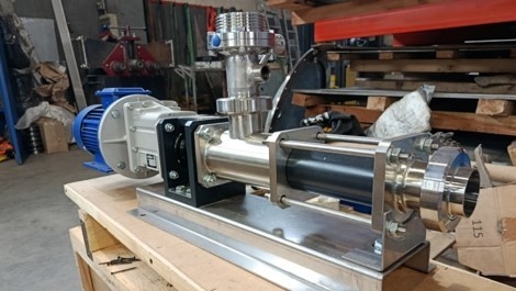
Screw pumps are used for pumping viscous liquids.
The operating principle is based on moving the liquid by means of a rotating screw inside the stator. They are also called progressive cavity pumps. Sealed chambers are formed between the screw and the stator. These chambers move the liquid from the inlet to the outlet without intensive mixing.
Application areas: food and chemical industries; oil and gas sector; construction; cosmetic industry.
Pumped products: creams, shampoos, liquid soap; sauces, honey, chocolate; fat, minced meat; crude oil and petroleum products; aggressive and viscous liquids; sludge, slurry, and much more.
We can manufacture a pump for any specific requirement.
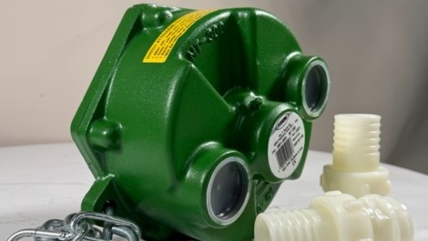
MT 300 roller pump , driven by the tractor power take-off (PTO) shaft.
This pump is not new to the market, but it continues to remain in demand — primarily because of its versatility and durability in field conditions.
Most common applications:
Field spraying
The pump is connected to the sprayer system and ensures stable delivery of the working solution. Suitable for applying: herbicides, pesticides, and liquid fertilizers.
Pumping technical liquids
Used for water, various solutions, and sometimes diesel fuel or other non-aggressive media.
Filling and emptying tanks
Convenient when working with tankers, barrels, and reservoirs in field conditions.
Washing machinery or equipment
How the roller pump works
The design is quite simple: inside the housing there is a rotor with rollers that create chambers of variable volume during rotation. This is what provides liquid suction and delivery.
The main feature is that the pump is powered by the tractor PTO. This means:
No separate power supply is required;
Stable operation even in the field;
Depends only on tractor RPM;
Can operate in reverse mode.
This makes the MT 300 максимально autonomous in operation.
Why it is efficient
Stable flow without pulsation
The roller system provides an even flow, which is especially important for spraying — the solution is delivered without pressure fluctuations.
Self-priming capability
The pump can operate without pre-filling the system, saving time during startup.
Easy maintenance
The construction is not overloaded with complex components — most servicing tasks can be performed without special tools.
Operation in field conditions
No dependence on electricity — only a tractor is needed. This is a key advantage for farmers.
Compactness and mobility
Easy to transport and quick to connect to machinery.
Important things to consider
Roller pumps have their own characteristics that should be understood before use:
Not designed for highly abrasive liquids;
Sensitive to dry running during prolonged operation;
The rollers should be checked periodically.
If basic operating rules are followed, the service life will be more than sufficient even under intensive use.
This pump is currently in stock, so you can confidently equip your machinery and start using it this season.
May 19, 2026
Spare parts for industrial and household pumps
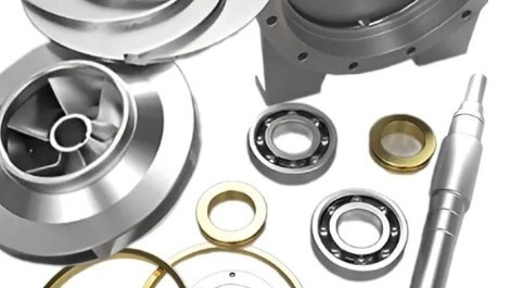
Honestly, most people start looking for pump spare parts only when the pump either stops pumping properly or stops working altogether. And in many cases, the problem is not as critical as it may seem at first. Sometimes it is enough to replace a seal or a few worn parts for the pump to continue operating normally without any issues.
We are often asked about spare parts for different types of pumps — domestic , borehole , circulation , drainage and sewage , as well as industrial models . Some customers are looking for an impeller, others need a shaft or a mechanical seal, and sometimes people simply do not know what exactly has failed. That is completely normal because not everyone deals with pumps every day.
Usually, customers just send a photo of the pump or the nameplate, and then we check the model to see what can be selected. Sometimes an original part is required, while in other cases a good-quality replacement is sufficient — it all depends on the situation and the equipment itself. Repair kits are also available because they are one of the easiest ways to restore a pump to proper operation without buying a new one.
There are also cases when the pump is already old and people think that spare parts are no longer available for it. However, quite often it is still possible to find either a compatible option or parts from another manufacturer that match the required parameters. That is why it is always better to check first rather than immediately writing the equipment off.
If you are not sure what exactly is needed — our managers will help you figure it out. Usually, a photo, the pump model, or simply a description of the problem is enough for selection.
May 18, 2026
AISI 304 Stainless Steel Butterfly Valves
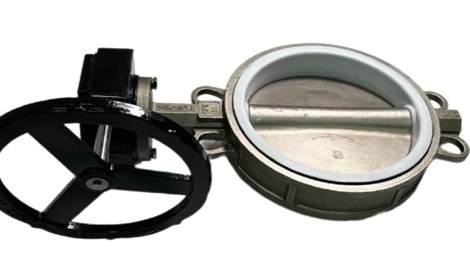
AISI 304 stainless steel butterfly valves are currently quite frequently ordered for water, various technical liquids, and industrial systems. Mainly because stainless steel handles moisture well and does not start rusting after a short period of time, as is often the case with cheaper alternatives.
In this model, both the body and the disc are made of AISI 304, while the seal is made of PTFE. In practice, this means the valve provides tight shut-off and operates reliably in the system without constant intervention or maintenance. This is important for many users, especially when equipment operates daily.
The advantage of a large-diameter butterfly valve with a worm gear reducer is the ability to operate it manually without significant physical effort, ensuring smooth opening and closing.
Most commonly used in:
pump stations;
irrigation systems;
fire protection systems;
main water supply pipelines;
wastewater treatment plants;
industrial pipelines.
There is nothing complicated about installation. The design is compact, which is why butterfly valves of this type are often installed where space is limited or where other equipment is already in place. The mechanism itself is simple and opens easily without unnecessary effort.
These butterfly valves can be found in industrial production, water supply systems, and even in some food processing applications. Everything depends on the medium and temperature conditions for which the valve is selected.
These valves are currently in stock. We can also offer other diameters and models for various applications and pipeline types.
May 16, 2026
A pump driven by the tractor's PTO
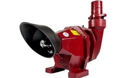
In farming and agricultural work, there are situations when water needs to be pumped quickly, but there is simply no access to electricity nearby. That is exactly why the MTZ-P 30-300 pump , which operates from a tractor PTO, is often used for such tasks. Connection takes very little time, and the pump itself can be used practically anywhere there is machinery available.
This model is commonly used for irrigation, filling tanks, supplying technical water, and various seasonal jobs. One of its biggest advantages is mobility, as the pump is not tied to one location. Today it can work near a reservoir, and tomorrow — already out in the field or at another site. For many users, this is much more practical than separate electric equipment.
These pumps are compatible with tractors such as: John Deere, Case IH, Ford, Massey Ferguson, Kentavr, Foton-Lovol FT504, Forte GT-181, XT-244, and others.
The MTZ-P 30-300 is not complicated to operate. Everything is quite straightforward: connect it to the tractor, start it up — and you are ready to work. That is why such pumps are often chosen by people who need simple and reliable equipment without unnecessary maintenance difficulties.
Another important point is the durability of the construction. The pump is designed for regular operation and handles conditions with dust, moisture, and constant workload without problems. This is especially important for agriculture, where equipment must work reliably throughout the season instead of simply sitting in the garage.
May 15, 2026
Methods for Installing Sewage Pumps
Proper installation is the key to efficient and reliable operation of the pump . Several main installation options are used for these pumps:
1. Stationary submersible installation
The most common option.
The pump is installed directly into a receiving tank (well or septic reservoir) and operates in a fully submerged condition.
Advantages:
stable operation;
efficient motor cooling;
minimal noise level;
long service life.
It is usually used together with automation systems (float switches), allowing the process to be fully automated.
2. Stationary installation with guide rails (rail system)
This makes it a more professional installation option.
The pump is lowered into the shaft along guide rails and automatically connected to the discharge pipe.
Advantages:
quick removal without descending into the well;
convenient maintenance;
personnel safety.
This is a good solution for hotels, residential complexes, and commercial facilities.
3. Mobile (temporary) installation
The pump is used as a portable unit — for example, for emergency pumping operations.
Advantages:
versatility;
the ability to quickly connect it wherever needed;
does not require complex installation.
It is especially relevant for service companies and construction work.
You can purchase the pump or get a free consultation simply by following this link .
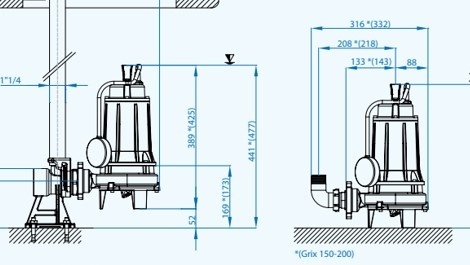
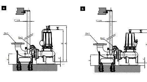
In wastewater drainage systems, it is not always possible to organize a gravity sewer system. This is especially relevant for basements, temporary structures, hotels, or facilities operating under increased load conditions.
One of these models is the Dreno GRIX 32-2/140 T — a reliable pump that combines high performance, durability, and a cutting mechanism system.
Pump purpose
The Dreno GRIX 32-2/140 T is designed for pumping heavily contaminated wastewater, including:
sewage water;
domestic wastewater;
liquids containing various inclusions (wipes, paper, organic residues).
The key feature of this model is the grinding system, which allows solid particles to be shredded before entering the pressure pipeline. This is especially important when small-diameter pipes are used or when there is a risk of clogging.
Application areas
This pump does not have a narrow specialization — on the contrary, it is versatile and suitable for various facilities:
1. Private houses.
If a bathroom or kitchen is located below the level of the central sewer system, such a pump becomes essential for proper operation.
2. Bomb shelters and shelters.
Under autonomous conditions and in limited spaces, it is important to have a reliable wastewater removal system. A grinder pump helps prevent clogging even during intensive use.
3. Hotels and recreation centers.
Heavy sewer loads and varying wastewater composition require stable operation without frequent maintenance.
4. Commercial facilities.
Cafes, service stations, and car washes — places where wastewater often contains foreign particles.
5. Temporary or mobile structures.
Construction camps, portable cabins, and modular houses — locations without a stationary sewer system.
You can purchase this pump directly via this link .
May 12, 2026
Updates to the design of magnetic pumps
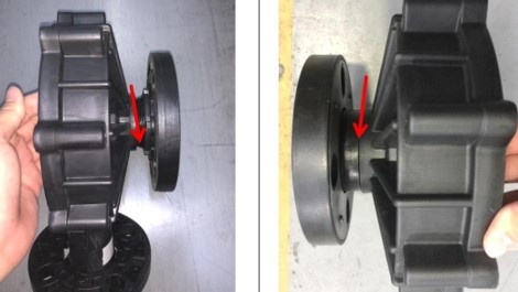
We would like to inform you about a minor design update of the QHX series magnetic pumps manufactured from PPH, PVDF, and CFRETE materials. The overall dimensions and connection sizes of the pumps remain unchanged, which will not create any issues for our customers when replacing the pump in the future. Details are provided below.
The QHX front cover has been upgraded from a “threaded + flanged design” to an integrated flanged structure manufactured by injection molding. Please find the update photos attached for reference. The inlet and outlet flanges have been upgraded from a bolted connection design to a one-piece molded structure, eliminating any risk of leakage at the flange connection points.
This update does not affect the performance or installation dimensions. It only improves sealing reliability and structural strength.
Conclusion: The purpose of this update is to optimize the product design, improve reliability, minimize the risk of leakage, and reduce maintenance costs.
Old flanged connection
New integrally injection-molded design
You can view or purchase these pumps using this link .