- Home
- Hydrants - water columns
Hydrants - water columns


PURPOSE OF THE PRODUCT AND PRINCIPLE OF OPERATION
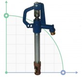
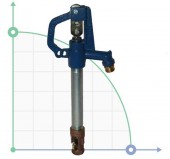
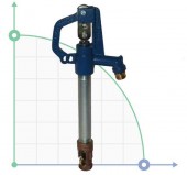
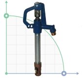
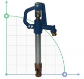
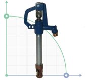
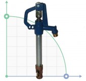
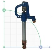
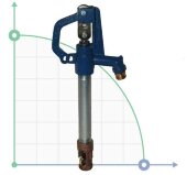
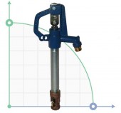
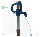
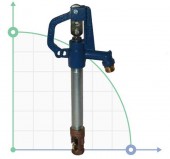
The hydrant column is designed for taking water from drinking water supply systems of households, rural and urban water supply systems.
Operating conditions:
- ambient temperature from -30 °C to +80 °C;
- the maximum pressure in the pipeline is 5.6 bar;
- operating pressure in the pipeline from 1.4 to 2.8 bar;
Execution material:
- body - galvanized steel;
- head - cast iron.
Design and operation
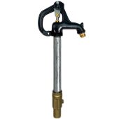
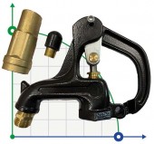
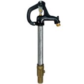
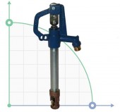
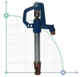
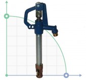
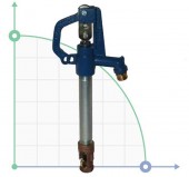
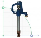
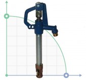
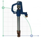
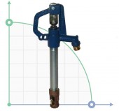
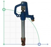
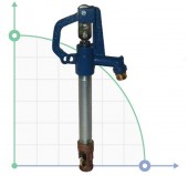
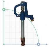
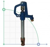
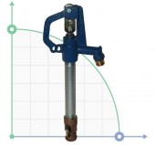
The column consists of a body with a stem located in it, a plunger valve, a branch pipe for connecting the pipeline and a handle (lever) for opening /closing the water column.
The column operates in two modes - open position, closed position. When you turn the handle up, the stem lifts the valve, opening the water supply and at the same time closing the drain hole. When lowering the handle the reverse process occurs - the stem pushes the valve, closing the water supply, at the same time opens drain hole through which the remaining water in the housing flows out through the drain hole, thereby preventing it from freezing.
| Model | Depth of occurrence, cm | Overall length, cm | Connection diameter | Drain hole diameter |
| BG-201 | 30 | 99 | 3/4-11.5NH | 1/8-27NPT |
| BG-202 | 61 | 130 | 3/4-11.5NH | 1/8-27NPT |
| BG-203 | 91 | 160 | 3/4-11.5NH | 1/8-27NPT |
| BG-204 | 122 | 191 | 3/4-11.5NH | 1/8-27NPT |
| BG-205 | 152 | 221 | 3/4-11.5NH | 1/8-27NPT |
| BG-206 | 183 | 251 | 3/4-11.5NH | 1/8-27NPT |
| BG-208 | 244 | 312 | 3/4-11.5NH | 1/8-27NPT |
| BG-210 | 305 | 373 | 3/4-11.5NH | 1/8-27NPT |
HOW DO FROST RESISTANT HYDRANTS WORK
|
CLOSED POSITION |
OPEN POSITION |
CLOSED POSITION - DRAINAGE |
|
Closed position - no water in the piping or riser head. The water stops plunger (valve) below the freezing depth of the soil. This type of protection prevents freezing. |
The plunger supplies water and seals the drain hole. NOTE: DO NOT REGULATE THE WATER FLOW. The hydrant handle must be in the FULL open position for proper water flow and reverse flow sealing. This type of hydrant will not work properly in a partially open position. |
Closing the handle pushes the plunger downward to stop the water flow and open the drain hole. it allows water in the head and pipe to flow back into the gravel drain ball. |

INSTALLATION OF THE HYDRANT CLONGE
Dig a pit for the hydrant installation with a diameter of about 70 cm and appropriate depth.
The depth of the excavation should be approximately 30 cm deeper from the place where the column is connected to the pipeline, for ease of installation and the possibility of installing the support.
The area of the column drainage hole should be located 10-15 cm below the level of soil freezing (see Fig. 1).
The level of soil freezing is determined according to DBN V.2.1-10-2009 and DSTU-N B V.1.1-27-2010.
For the territory of Ukraine, the average value of the depth of soil freezing is from 0.8 to 1.3 m.
- Flush the pipeline before connecting the column. Make sure there is no debris or foreign objects which can collect in the pipeline during installation and assembly.
- Install a support made of concrete elements or bricks under the pipeline to prevent its subsidence.
- Connect the column to the pipeline. Test column performance by opening and closing the handle several times. Make sure that there are no leaks at the connection, proper drainage when closing the Column, and leaks from the drainage hole after water discharge.
- Fill the cut with medium gravel to create a drainage layer. Before backfilling, make sure drainage occurs without difficulty.
- If the hydrant is installed in a utility room, or on an asphalt or concrete road, organize drainage by connecting the tube to the drainage hole of the column, to drain the discharged water into well-drained soil layer or sewer.
MAINTENANCE OF THE HYDRANT COLUMN
Column adjustment:
- Turn off the water supply.
- Open the hydrant column to the fully open position using the handle to relieve residual pressure.
- Unscrew the set screw.
- Lower the column handle until the plunger touches the supporting surface.
- Turn the handle about 30 ° from the closed position.
- Tighten the set screw tightly and lower the handle to the fully closed position.
- Turn on the water supply.
- Open the column to the fully open position and make sure that there is no leakage from the drain hole.
- Close the column and check that there is drainage.
- If the drain hole does not completely close off, repeat the above steps.
Cleaning the drain hole
If the drain hole is clogged, it should be flushed.
To clean the drain hole, close the column spout with the stopper. Open the column and close it, to flush the drain hole under pressure.
If an attempt to flush the column under pressure does not give the desired result, adjust the column.
| Pipe material | painted steel |
| Producer | BTS Engineering |
| Model | BG-203 |
| Submersible part length, mm | 910 |
| Length, mm | 1 600 |
| Pipe material | zinc-coated steel |
| Producer | BTS Engineering |
| Model | BG-203 |
| Submersible part length, mm | 910 |
| Length, mm | 1 600 |
| Pipe material | zinc-coated steel |
| Producer | BTS Engineering |
| Model | BG-205 |
| Submersible part length, mm | 1400 |
| Length, mm | 2 210 |
| Producer | BTS Engineering |
| Model | BG-101 |
| Submersible part length, mm | 300 |
| Length, mm | 990 |
| Producer | BTS Engineering |
| Model | BG-102 |
| Submersible part length, mm | 610 |
| Length, mm | 1 300 |
| Producer | BTS Engineering |
| Model | BG-103 |
| Submersible part length, mm | 910 |
| Length, mm | 1 600 |
| Producer | BTS Engineering |
| Model | BG-104 |
| Submersible part length, mm | 1 220 |
| Length, mm | 1 910 |
| Producer | BTS Engineering |
| Model | BG-105 |
| Submersible part length, mm | 1 520 |
| Length, mm | 2 210 |
| Producer | BTS Engineering |
| Model | BG-106 |
| Submersible part length, mm | 1 830 |
| Length, mm | 2 510 |
| Producer | BTS Engineering |
| Model | BG-108 |
| Submersible part length, mm | 2 440 |
| Length, mm | 3 120 |
| Producer | BTS Engineering |
| Model | BG-110 |
| Submersible part length, mm | 3 050 |
| Length, mm | 3 730 |
| Producer | BTS Engineering |
| Model | BG-201 |
| Submersible part length, mm | 300 |
| Length, mm | 990 |
| Producer | BTS Engineering |
| Model | BG-202 |
| Submersible part length, mm | 610 |
| Length, mm | 1 300 |
| Producer | BTS Engineering |
| Model | BG-204 |
| Submersible part length, mm | 1 220 |
| Length, mm | 1 910 |
| Producer | BTS Engineering |
| Model | BG-206 |
| Submersible part length, mm | 1 830 |
| Length, mm | 2 510 |
| Producer | BTS Engineering |
| Model | BG-208 |
| Submersible part length, mm | 2 440 |
| Length, mm | 3 120 |
| Producer | BTS Engineering |
| Model | BG-210 |
| Submersible part length, mm | 3 050 |
| Length, mm | 3 730 |
| Producer | BTS Engineering |
| Model | BG-301 |
| Submersible part length, mm | 300 |
| Length, mm | 990 |
| Producer | BTS Engineering |
| Model | BG-302 |
| Submersible part length, mm | 610 |
| Length, mm | 1 300 |
| Producer | BTS Engineering |
| Model | BG-303 |
| Submersible part length, mm | 910 |
| Length, mm | 1 600 |
| Producer | BTS Engineering |
| Model | BG-304 |
| Submersible part length, mm | 1 220 |
| Length, mm | 1 910 |
| Producer | BTS Engineering |
| Model | BG-305 |
| Submersible part length, mm | 1 520 |
| Length, mm | 2 210 |
| Producer | BTS Engineering |
| Model | BG-306 |
| Submersible part length, mm | 1 830 |
| Length, mm | 2 510 |
| Producer | BTS Engineering |
| Model | BG-308 |
| Submersible part length, mm | 2 440 |
| Length, mm | 3 120 |
| Producer | BTS Engineering |
| Model | BG-310 |
| Submersible part length, mm | 3 050 |
| Length, mm | 3 730 |
| Producer | BTS Engineering |
| Model | BG-401 |
| Submersible part length, mm | 300 |
| Length, mm | 990 |
| Producer | BTS Engineering |
| Model | BG-402 |
| Submersible part length, mm | 610 |
| Length, mm | 1 300 |
| Producer | BTS Engineering |
| Model | BG-403 |
| Submersible part length, mm | 910 |
| Length, mm | 1 600 |
| Producer | BTS Engineering |
| Model | BG-404 |
| Submersible part length, mm | 1 220 |
| Length, mm | 1 910 |

