Valve plates, mesh plates, cap plates, ballast plates
Basic cymbal designs
Mesh plates.
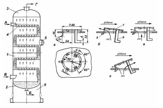
A column with mesh plates (Fig. 1) is a vertical cylinder with horizontal plates fixed to support beams, in which a large number of holes with a diameter of 2 to 8 mm are drilled evenly over the entire surface. Sometimes stencils may have different hole sizes depending on the type of product being processed on the board. Therefore, for weak nitric acid pipelines, tower devices are produced equipped with mesh plates with 0.8 mm holes.
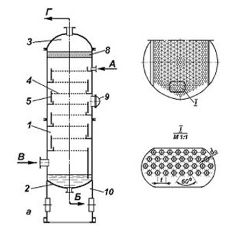
Rice. 1 - Column with mesh plates
a - column structure; b - structure of the mesh plate Flows: A - liquid inlet; B - liquid output; B - gas inlet; G - gas outlet 1 - housing; 2 - bottom; 3 - cover; 4 - mesh plate; 5 - overflow wall; 6 - plate canvas; 7 - overflow strip; 8 - splash trap; 9 - hatch - manhole; 10 - support
The gas passes through the holes in the plate and is distributed in the liquid in the form of small jets and bubbles. The gas must move at a certain speed and have sufficient pressure to overcome the pressure of the liquid layer on the plate and prevent liquid from flowing out through the holes in the plate.
Under normal operating conditions, liquid does not pass through the hole because it is supported by gas pressure below. At low gas loads, the gas pressure is not able to maintain a layer of liquid on the plate corresponding to the overflow height. In this case, the liquid level is set below the overflow port and the liquid passes through the same holes as the gas, that is, the plate operates in failure mode. This is a non-operating operating mode for the specified dish.
Mesh trays are mainly used for the distillation of alcohol and liquid air. Its permissible load of liquid and gas (steam) is small, and the operating mode is difficult to regulate. The transfer of mass and heat between steam and liquid occurs mainly through a layer of foam and spray at some distance from the bottom of the plate.
Screen panels are characterized by simplicity and ease of installation, inspection and maintenance. The width of individual panels sections allows them to be installed or removed through column hatches. These plates have very low hydraulic resistance. Mesh trays operate stably in a fairly wide range of gas velocities, and in a certain range of gas-liquid loads they have high efficiency.
At the same time, mesh plates are sensitive to dirt and deposits that clog the pores of the plates. If the gas supply suddenly stops, all liquid will be drained from the network and the tower will need to be restarted to resume operation.
Mesh plates must be installed strictly horizontally so that steam passes through all the holes in the mesh and no liquid passes through them.
Kovpachka plates.
The main component of a column with cap plates is a vertical cylinder 1, which is completely welded or assembled in separate zones (drawbars) (Fig. 2). In this case, multi-cap overflow trays 4 are installed at a certain distance from each other. The distance between the trays is determined by the work process parameters and the diameter of the column.
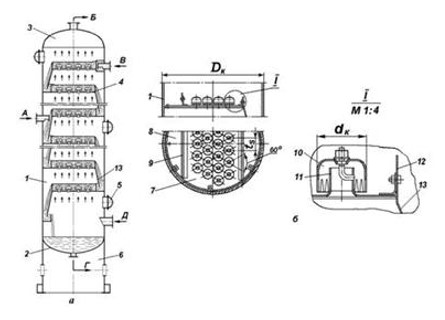
Rice. 2 - Column with cap plates
a - column structure; b - structure of a cap plate with segmental overflows;
Flows: A - supply of the initial mixture; B - steam exhaust; B - liquid supply;
G - drainage of bottom liquid; D - steam supply from the evaporator;
1 - column body; 2 - bottom; 3 - cover; 4 - cap plate with segmental overflows;
5 - hatch - manhole; 6 - support; 7 - plate canvas; 8 - receiving pocket; 9 - overflow strip;
10 - capsule cap; 11 - steam pipe; 12 - drain strip; 13 - drain sheet
Cap plates are a canvas with a nozzle that is closed on top with a lid. Liquid flows from tray to tray through the overflow, and the level on the tray is set at the top edge just above the drainage threshold. The bottom of the overflow device is below the liquid level, forming a hydraulic valve that prevents gas from passing through the overflow hole (Figure 2).
Liquid poured from the upper plate to the lower one moves horizontally along the plate. To ensure that liquid flows only from the overflow and not from the outlet, the top edge of the outlet must be higher than the level of the liquid on the plate.
The cap is immersed in the liquid at its lower end. The gas enters the space under the cap through the nozzle, passes through the layer of liquid and exits in the form of bubbles from under the cap.
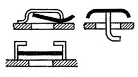
The main difference between cap plate designs is the cap design. Caps can be round, rectangular or tunnel-shaped. At the lower end of the cap there is a triangular, rectangular or trapezoidal slot 20-30 mm high. The main purpose of the slots is to eliminate the one-way flow of gas from under the hood if the plane of the lower end moves from the horizontal due to misalignment during installation.
During operation of the column, the slots in the packing must be completely immersed in the liquid to a depth of 10-20 mm below the surface of the liquid on the tray, which ensures that the gas flow is dispersed and bubbles through the liquid layer.
The cap is installed with a certain gap in relation to the plane of the plate.
The dimensions of the steam nozzle and cap are standardized and selected in accordance with the diameter of the column. The standard diameters of the nozzles depend on the diameter of the steam nozzle and are 60, 80, 120 and 150 mm, respectively. There can be a large number of caps on the plate, the so-called multi-cap trays.
Single-cap plates with one large diameter cap (about 2 m) are used, for example, when working with contaminated liquids (soda industry).
Single-cap plates are less susceptible to contamination and have a longer service life. Their peculiarity is that if the gas supply suddenly stops, the liquid does not drain from the plate, and it starts working again when the gas supply is resumed. First, liquid is supplied to the trays, which leads to a gradual accumulation of liquid on all the trays from top to bottom. This creates a water seal in the overflow pocket. Then gas is supplied. First, a layer of bubbles appears on the bottom tray, then on the second tray from the bottom, and gradually the entire column begins to work .
These are the most common plates and are widely used in both distillation and absorption processes.
The schematic diagram of the capsule plate is shown in Fig. 3.
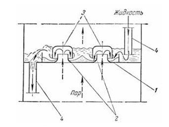
Rice. 3 - Scheme of operation of the cap plate
1 - plate; 2 - gas pipes; 3 - caps; 4 - drain pipes
The plate has a positive opposite drainage system (tube). Gas (steam) passes through the gas nozzle, is reflected from the inner surface of the cap, returns down, enters the liquid layer through the grooves and breaks into numerous jets that foam the liquid.
The height of the gas foaming layer depends on the size of the nozzle, the depth of immersion, the steam velocity, the thickness of the liquid layer on the tray and the physical properties of the liquid.
Valve trays.
The main assembly unit of a column with valve trays is a vertical cylindrical body 1, manufactured by an all-welded or detachable method (Fig. 4). Overflow plates 4 are installed in the housing at equal intervals from each other. The distance between the plates is determined depending on the technical parameters of the operation and the diameter of the column.
Rice. 4 - Structure and principle of operation of a column with valve trays
Flows: A - liquid supply; B - fluid drainage; B - supply of gas mixture; G - gas outlet;
a - the structure of the lift-and-swing valve; b, c, d - valve position at minimum, average and maximum loads, respectively;
1 - column body; 2 - bottom; 3 - cover; 4 - valve plate; 5 hatch - hole; 6 - support; 7 - valve disc; 8 - short restrictive leg; 9 - long restrictive leg
The valve plate is a sheet with holes, each of which is closed by a movable plate. Under its own weight, the plate closes the holes and prevents the free passage of steam. When starting these trays, as with the cap tray, liquid is first introduced to form a layer on the tray. Then steam is supplied. The steam flow creates pressure under the tray and the cap rises, creating a channel for the gas to escape. Depending on the load, the valve is mixed in a vertical plane, changing the active cross-sectional area through which gas passes, with the maximum cross-sectional area determined by the height of the legs, which limit the lifting of the valve. The gas penetrates the layer of liquid, creating a layer of bubbles on the plate.
The greater the gas flow, the higher the valve rises. Therefore, these trays operate effectively over a wide range of gas loads and are resistant to gas load fluctuations. They have also proven to be highly efficient even at long load intervals thanks to their self-regulating function.
The principle of operation of the tray is that the valve, hanging freely over the holes in the tray, under the influence of its own weight, automatically adjusts the size of the gap between the valve and the surface of the tray in response to changes in gas flow, maintaining the flow rate of gas entering the bubble layer at a constant level . This leads to a slight increase in the hydraulic resistance of the valve disc. The valve lift height usually does not exceed 8 mm.
The active cross-sectional area of the gas hole is 10-15% of the cross-sectional area of the column. The gas flow speed reaches 1.2 m/s. The valve can be located on the top side (fig. left) or bottom (fig. right) in the form of a round or rectangular plate with a lift limiter.
Rice. 5 - Valve design
We can say that valve plates are a modification of mesh plates, adapted to work under highly variable gas loads.
The valve tray is an improved version of the mesh tray which can be said to be able to handle highly variable gas loads.
Ballast valve discs.
Ballast valve plates are a type of valve plate (Fig. 6, d)
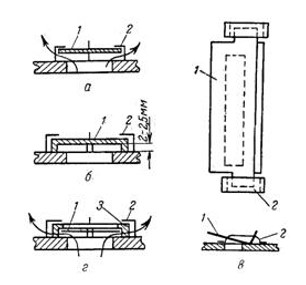
Rice. 6 - Types of valves
a, b - with round valves; c - with a plate valve; g - with ballast valve
1 - valve; 2 - bracket-limiter; 3- ballast
These plates differ from valve plates in that a heavy valve is mounted between the light valve and the limit bracket, and another heavy valve is mounted on a short post on the plate. The valve begins to rise at low gas speed. With a further increase in gas speed, the valve rests on the ballast and then rises with it.
The ballast plate works in two stages. Due to its low weight, the valve opens at low gas loads. Under heavy loads, the valve rests on the ballast and rises with it.
Ballast plates are characterized by more uniform operation and a complete absence of drops over the entire range of gas speeds.
Advantages of valves and ballast plates: relatively high flow capacity and hydrodynamic stability, constant and high efficiency over a wide range of gas loads. This is a distinctive feature compared to all other plates.
Tests of ballast plates have shown stable operation even when the gas load changes by a factor of 10.
 1600 mm column valve plate for alcohol rectification")
| Producer | BTS Engineering |
| Material | AISI 321 |
| Max.temperature, C | 300 |
| Height, mm | 170 |
| Diameter, mm | 1 600 |

| Producer | BTS Engineering |
| Material | AISI 321 |
| Max.temperature, C | 300 |
| Height, mm | 500 |
| Diameter, mm | 2 000 |

| Producer | BTS Engineering |
| Material | AISI 304 stainless steel |
| Max.temperature, C | 300 |
| Diameter, mm | 1 200 |
| Distance between button mm | 170 |

| Producer | BTS Engineering |
| Material | AISI 304 stainless steel |
| Max.temperature, C | 300 |
| Diameter, mm | 600 |
| Distance between button mm | 170 |

| Producer | BTS Engineering |
| Material | AISI 304 stainless steel |
| Max.temperature, C | 300 |
| Diameter, mm | 800 |
| Distance between button mm | 170 |

| Producer | BTS Engineering |
| Material | AISI 304 stainless steel |
| Max.temperature, C | 300 |
| Diameter, mm | 1 000 |
| Distance between button mm | 170 |
 valve plate 1400 mm for distillation, rectification, cracking processes")
| Producer | BTS Engineering |
| Material | AISI 304 stainless steel |
| Max.temperature, C | 300 |
| Diameter, mm | 1 400 |
| Distance between button mm | 170 |

| Producer | BTS Engineering |
| Material | AISI 304 stainless steel |
| Max.temperature, C | 300 |
| Diameter, mm | 1 800 |
| Distance between button mm | 170 |

| Producer | BTS Engineering |
| Material | AISI 304 stainless steel |
| Max.temperature, C | 300 |
| Diameter, mm | 2 200 |
| Distance between button mm | 170 |

| Producer | BTS Engineering |
| Material | AISI 321 |
| Max.temperature, C | 200 |
| Diameter, mm | 1 400 |
| Distance between button mm | 250 |

| Valve thickness, mm | 2 |
| Number of valves, pcs | 48 |
| Relative free passage area, % | 7,76 |
| Producer | BTS Engineering |
| Material | AISI 321 |

| Valve thickness, mm | 2 |
| Number of valves, pcs | 48 |
| Relative free passage area, % | 7,76 |
| Producer | BTS Engineering |
| Material | AISI 321 |

| Valve thickness, mm | 2 |
| Producer | BTS Engineering |
| Material | AISI 321 |
| Max.temperature, C | 200 |
| Diameter, mm | 1 600 |

| Valve thickness, mm | 2 |
| Producer | BTS Engineering |
| Material | AISI 321 |
| Max.temperature, C | 200 |
| Diameter, mm | 1 500 |

| Producer | BTS Engineering |
| Material | AISI 321 |
| Max.temperature, C | 200 |
| Diameter, mm | 1 400 |
| Distance between button mm | 340 |

| Valve thickness, mm | 2 |
| Producer | BTS Engineering |
| Material | 0Cr13 |
| Diameter, mm | 48x2 |
| Valve type | EDV |

| Valve thickness, mm | 2 |
| Producer | BTS Engineering |
| Material | C276 |

| Size | DN80 |
| Producer | BTS Engineering |
| Material | медь |
| Country of Origin | China |

| Size | DN100 |
| Producer | BTS Engineering |
| Material | медь |
| Country of Origin | China |

| Size | DN150 |
| Producer | BTS Engineering |
| Material | медь |
| Country of Origin | China |

| Size | DN80 |
| Producer | BTS Engineering |
| Material | нержавеющая сталь |
| Country of Origin | China |

| Size | DN100 |
| Producer | BTS Engineering |
| Material | нержавеющая сталь |
| Country of Origin | China |

| Size | DN150 |
| Producer | BTS Engineering |
| Material | нержавеющая сталь |
| Country of Origin | China |

| Size | ф51x3 mm |
| Producer | BTS Engineering |
| Material | AISI 316L |
| Country of Origin | China |